What's new
What's new

Electrical idiot with a Wiad

gleek

Aluminum
Joined
Feb 28, 2012
Location
cookeville,tn
First I'd like to thank everyone that helped getting my MG up to speed.Just had it sold while away(long story not needed).
Anyway I knew where there was another Monarch EE (45878)was tucked away and it's in my shop now.
From all the threads I've looked through it's a Wiad (1962). I'm sure with some HELP this sweethart will run for another 50 years.
although when I put the power to it,the main contactor won't stay pulled in,also the 3amp fuse is blown every time I atempt to push the"Control on"switch.I've wired 220 single phase(L1 and L3) I don't have a pump so it looks like L2 isn't used.I have the original electrical blueprints,they were still in there from 1962.This is a good thing,but,I look like the RCA dog staring at the speaker when I look at these prints.WHAT is a FA or a FL for starters? Should the FL close before main contactor can pull in and what kind of a gap should these contacts have? Mine is about 3/16
Also at start-up the tubes heat up but they don't"glow",is this another problem??
Being a mental midget when it comes to electricity is there any procedure out there to start checking like a checklist until you find the problems or just every component one at a time.

thanks
Gleek
 

Attachments

  • 051812185712.jpg
    051812185712.jpg
    95 KB · Views: 431
One suggestion to get you started, approach the problem with the flow of electricity. Now I am not familiar with your lathe at all so take this with a grain of salt, although it is kinda like trouble shooting 101. Frist observe all electrical safety protocols, then disconnect the wires leading from the main contactor (just before it reaches any other items. Now this maybe tricky but put power to main contactor; does it pull in and hold ? yes-->then conect the next compont and so forth. No--> main contactor wired incorrectly or unit is faulty.
Now this just bare bones with out having eye balls on the lathe or schematic adds a degree of challenge.

Non the less,
Cheers and good luck
Doug
 
I have s/n 45802 - yours is definitely a modular. FA = Field Acceleration relay. FL = Field Loss relay.

Mine blows fuses on occasion. I finally replaced all the old solid state rectifier diodes in the module, as that was the cause in two out of three fuse blowing events. (The other was caused by a shorted cooling fan motor).

Not sure what you mean by "main contactor".
 
Thanks for the corection I just know whatever EE I can get running I'll have somthing.
by "main contactor" it should be power contactor(PC) on print.I'll check out diodes in the in module and get back,also the fan has been replaced with a later one,I'll check wiring.
thanks
gleek
 
The fan wiring and filter seem fine but the power comes from the timer,I figure somebody just got the new fan going,then left it.
I removed the spindle module and went right over my head,do I have to desolder the diodes to test and how do I test the capacitors?
 
What I thought were a diode were really a resistor so that being said I did find two bad ones,and they're on the circut that the 3amp fuse is on.At the electronics store they gave me a cross reference diode.Did you solder these new ones or go find the old stock like in e-bay?
 
I soldered mine in. Make sure the new ones go in the same direction as the old ones. (there's a polarity mark on diodes - pay attention...) I used 1000V, 1A diodes, because that's what was handy, but you don't need that high of a voltage rating - 400V or more would probably do.
 
I soldered mine in(polarity noticed) and the 3amp fuse blew agin.I called monarch and talked to Steve in service,he said it could be the small vacum tube,which I ordered.I hope throwing money at this isn't the answer.
 
The diodes, are removable for good reason.
For example, diodes in rec 3, and some of the others can get hot and degrade over time, they cant be tested when soldered in.
Other problems can happen down line in the multitude of switches, or other components that can quickly be found by a blown or weakened diodes.
 
I removed soldered diodes and they tested bad.
Could I have this wired wrong?The only place I saw to change 460 to 220 was the jumpers in the T5 connections. Is there any other places like T6 or T7 ?
 
I've not had to convert a 460 machine to 230. But a quick glance at the schematic shows that T5, T6, and T7 all have dual voltage primaries. Additionally, the shunt at T1 and T2 needs to be changed.
 
I had already changed the shunt length on T1 T2 from a note on the print.
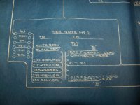
What am I looking at on T6,and T7 ? Do I have to swich wires I don't understand this 001.jpg002.jpg003.jpg
 
"The only place I saw to change 460 to 220 was the jumpers in the T5 connections. Is there any other places like T6 or T7 ?"

The machine comes equipped with 230 volt (250 maximum) transformers OR 460 volt (500 maximum) transformers. The schematic diagram is unclear in that it mentions BOTH 230 (250) AND 460 (500), but in reality it is ONLY 230 (250) OR 460 (500).

It is possible to series connect a pair of 230 volt transformers so as to operate on 460 volts. The special procedure for doing this is in a "sticky".

It is not possible to connect 460 volt transformers to operate on 230 volts.

The remaining transformers are 230/460 volts.

The change in the shunt is required, too, but you have already done that.

As the total capacity of the C16J filaments is about 165 V-A, a 250 V-A control transformer may be employed to effect any needed change in the supply to the two C16J filament transformers.

A common 115/230:230/460 control transformer would do the job nicely, with the low side wired for 230 and the high side wired for 460.

Then, simply interpose the control transformer between the source and the C16J filament transformers.
 
400 500.jpgWhat are my options? What Peterh talks about is way over my head,but I have Tenn. Tech here in town and can get someone to help me thru.
 
The option is simple, this is merely a rewording of what Peter said.

Obtain a .250 KVA 240v to 480 v control transformer. Often these are rated for multiple voltages by connecting their internal windings differently but they will come with specific instructions to do so, it's simple connect the numbers as the instructions show. These transformers can be used to either step up voltage or step down a voltage. Here it will be used to step up the voltage from your 240 line voltage to supply 480 v input to the original filament transformers.

Prices vary, I've bought them surplus for a few bucks, brand new full on top drawer retail (think Grainger and similar) they might cost ~$150 or so. I haven't looked but MMC most likely has them for retail and it's difficult to beat their service.

Disconnect the input power feed lines to your present filament transformers. Connect the input supply that originally supplied the input to the two transformers from the machine to the 240 v volt input side of a .25 KVA rated step up transformer (KVA is the electrical capacity rating of the transformer). From the new 240 v to 480 v step up transformer connect the 480 v output to the input connections of each of the original Monarch transformers.

Electrically that's all there is to it. Of course the new transformer should be properly mounted and grounded. Use at least 16 gage stranded wire rated for at least 600 v with proper end connectors and route the wires out of harms way. Emulate how Monarch did the connections and it will be good.


Back
Top