What's new
What's new

KB DC drive success. so far at least...

bll230

Hot Rolled
Joined
Jun 14, 2007
Location
Las Vegas
With regards to Bill, and I have already purchased the Parker/Eurotherm drive combo on his and Mark's advice, I have wondered for some years whether the KB PWM controls would work on the Monarch. I use the KB PWM controls with PM motors on my SB9, SB10L, and Clausing 8520 mill and have been more than satisfied with their smoothness and power.

I am using a KBWT-210 for the armature and a KBWT-26 for the field, both 240 VAC input.

IMG_0240.jpg

Ignore the rats nest wiring, I just wanted them mounted where I could get to them easily and connect to my test panel. If they do prove successful, I'll probably mount everything on a homemade drawer on the WIAD slides.

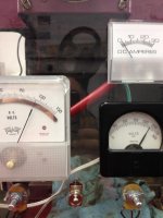
At nominal voltages, 230 VDC armature, 115 VDC field, I get nominal RPM.

IMG_0235.jpgIMG_0237.jpg

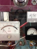
And these are the values at 4000 RPM

IMG_0238.jpgIMG_0239.jpg

The KBWT-210 will go to just over 240 volts, so it has the reserve for the IR compensation to be effective. The unknown at this point is how much load I will put on the machine. I don't plan on taking 1/4 cuts in steel. In the coming months as I get the lathe back together I'll measure loads for different cuts. I'll have my completely rebearinged apron on the lathe in a couple of days, the gearbox and ELSR assembly will probably be a few more months. Since as I have mentioned I can make my own gears, I have designed a coupling device that will operate both pots properly with one knob. That will be my next project after the apron. With regards to reversing, I think I will just wire in relays myself like the WIAD circuit, that way I can reverse the armature, but keep the series field at the same polarity.
 
Since the drive is not a 4 quadrant like the SCR KBRG is you will need some form of anti plugging to prevent switching polarity of the armature voltage while the motor is still spinning. This is referred to as the AP relay.

Another Bill
 
I have wondered for some years whether the KB PWM controls would work on the Monarch. I use the KB PWM controls with PM motors on my SB9, SB10L, and Clausing 8520 mill and have been more than satisfied with their smoothness and power.

I am using a KBWT-210 for the armature and a KBWT-26 for the field, both 240 VAC input.

I use 'many' KB drives here. Nine of them, IIRC.

But ... on 180 VDC motors. Of 1 to 4 HP. That are ALL rated for 'Rectified Power.

Actually, all but one of them are "Rolls Royce" grade Reliance "RPM III", a lone Baldor/ T.B.Woods that is at least also "SCR Duty" rated is the odd-man-out, and a relative POS by comparison.

PWM Duty is a higher motor spec yet. KB show that in their own data sheets. More pulses. Faster rise and fall times. Onboard Capacitors can only clean that up when run well within spec, not out at the raggedy edges. Note their full 1 HP drop from PWM rated motor to SCR-rated motors

And .... you really should put more faith in KB's specs. They are 'honest' enough.

:)

The 3 HP "large frame" Reliance motor for the 10EE motor doesn't meet either SCR or PWM duty specs, BTW. On fast-switching Solid State Drives it NEEDS the protection of at least a filter choke for either of PWM or SCR, if not-also the far, far heavier "ripple filter" choke ration of inductance for the smoother but "lumpier" pulsed DC off an SCR-class DC Drive.

The 3 HP and 5 HP "Small frame" motors are SCR-duty rated, but not PWM rated.

Yes, you can "make turns" with a woefully under-spec DC Drive. At ZERO load.

But for real-world work? Your South Bend and its belted ratios will do far the better job than a 10EE on starvation rations can do.

Some make chips. Some make tests. The late Harry Bloom did both, and wrote a pair of PM threads covering this very issue - more than a dozen years ago. Missed that thread, sadly, so started out with KB drives here meself (4Q KBRG-255 5 HP but only 180 V). Came to SSD's later.

So...BTDTGTTSWBH ("With Bullet Holes") in the form of receipts for multiple thousands of dollars along the way.

Feel free to duplicate some part of that. There is a certain amount of "fun" in it.

And - no great loss - your KB drives can always be re-purposed to drive a small mill, drillpress, grinder, belt-sander, sawdust-maker, attic fan, paint-stirrer ..even yet-another SB or Clausing.

Oh.. and Monarch/Reliance DID "cheat". That 'nominal' 3 HP large-frame motor? Four-point-five or so, and near-as-dammit TWICE the torque of even the later 5 HP motors, the way they actually ran it. Thass why they NEEDED 5 HP DC to replace a nominal 3 HP.

The original "war horse" was, and IS, happy with 260 VDC, wants 16 to 20 Amps handy for peak torque, needs those available for good regulation, even when not fully loaded. End of the day (well several years part-time, actually) I couldn't see "crippling" any of that.

As will (again) be demonstrated if you will be kind enough to keep at it for the next few steps. A 'scope would be handy....

And yer gonna LOVE the Parker-SSD's by comparison. So long as you give them BOTH the input voltage boost and the ripple filter needed, output side, anyway.

:)
 
Since the drive is not a 4 quadrant like the SCR KBRG is you will need some form of anti plugging to prevent switching polarity of the armature voltage while the motor is still spinning. This is referred to as the AP relay.

Another Bill

Yup.

With any 1Q drive, even a Parker-SSD 512 not 514, one needs near-as-dammit the FULL functionality of the original Monarch DC Panel.

Beel/BICL D510 1Q drives at least provided their own substitute for that.

KB - or any of a dozen other - 1Q drives do not have that.

They ALSO "do not have" - nor did the D510 - quite the same high level of protection needed against something the the old MG, WiaD, and Modular drives survived and ignored with nary a whimper. The ability to survive some right serious braking, shut-down, or reversing CEMF "spikes".

For 1Q drives, the 10EE OEM goods need to be retained, repaired, kept in good working order - even augmented with specialized MOV's or the like, lest the solid-state DC Drive dies a nasty death.

The 480 Volt input capable SSD drives are rather better protected on that score for sub 400 VDC outputs. KB drives don't (yet) include 480 V goods, nor over 260 VDC outputs. Basically, they are 240 VAC in, 180 VDC out, only "sometimes" with a bit of a stretch.

More valuable yet is that a(ny) decent 4Q implementation doesn't MAKE such outrageous spikes to begin with.

Wot hitandmiss said, IOW..

:)
 
Thanks for the input. Bill, can you explain what "SCR rated" and "PWM rated" actually means??? The PWM has a form factor of <1.05, whereas SCR apparently is almost 1.5.

As I mentioned I am going to wire in the relays for reversing. I discussed with KB using an APRM-PC and an APRM-3 board, wasn't comfortable with either after talking to them so decided to brute force it. All it takes is the anti-plug relay and a forward and a reverse relay. Not a big deal.

That does bring up another question. Can someone tell me what the forward and reverse contactor voltage is on a WIAD. The module circuit diagram shows 115 VAC control voltage, but I don't have a good WIAD circuit diagram, just the one of the internet. This came up because my gearbox lock solenoid is inop. I am aware that this is an indication that I have way too much free time, but I was thinking of rewinding the solenoid, I just need to know what voltage it was originally operated with.

Thanks again for the info.
 
Thanks for the input. Bill, can you explain what "SCR rated" and "PWM rated" actually means??? The PWM has a form factor of <1.05, whereas SCR apparently is almost 1.5.
Switching artifacts. A 'scope will show them. Those can damage windings and 'flute' roller bearings from corona discharge, older motors most of all. Takes more to filter rough-as-a cob 1-P derived Dee Cee than 3-P AC off a Vee Eff Deee. PWM Dee Cee is sort of 'in between'. Think VFD with output rectified back to DC. "Sort of" anyway.

As I mentioned I am going to wire in the relays for reversing. I discussed with KB using an APRM-PC and an APRM-3 board, wasn't comfortable with either after talking to them so decided to brute force it. All it takes is the anti-plug relay and a forward and a reverse relay. Not a big deal.
Time will tell.. again.. I've got Mercury Displacement Contactors laid by for that sort of use. Bitchin' to have no exposed arcs or contact wear, but you have to be careful with 'em. Very careful.

:)

That does bring up another question. Can someone tell me what the forward and reverse contactor voltage is on a WIAD. The module circuit diagram shows 115 VAC control voltage, but I don't have a good WIAD circuit diagram, just the one of the internet. This came up because my gearbox lock solenoid is inop. I am aware that this is an indication that I have way too much free time, but I was thinking of rewinding the solenoid, I just need to know what voltage it was originally operated with.

Thanks again for the info.

Rare 220 Volt or three, MG-era, around, otherwise 115 nominal it is - MG onward. Tapped off the Field Power supply, rotating or otherwise BEFORE "field Weakening" that uses the rest of it, same upstream source.

And nooo 90 VDC under load is not good enough for the field, even if the contactors tolerate it. Hence the Parker-SSD 50X, 230 VAC input.

I have ZERO relays or contactors, but run my Field at up to 140-144 VDC for braking, accel, and heavy-lifting. Just the reverse of Field Weakening. More torque, y'see.

On the other. Cheaper to buy a solenoid.

Once FIRED an MSEE over that sort of s**t. Could NOT get him to understand that the custom-wound "five volt" solenoid he thought he HAD to have on a classified Gummint project was just as well-served with a stock 6 V solenoid, de-rated pull.

Mind - the rest of his design was a bigger disaster, yet.. no solenoid needed atall.. so.... guess 5 or 6 years of Collitch means one is "educated" well-enough.

Just not necessarily SMART.
 
Since as I have mentioned I can make my own gears, I have designed a coupling device that will operate both pots properly with one knob. That will be my next project after the apron. With regards to reversing, I think I will just wire in relays myself like the WIAD circuit, that way I can reverse the armature, but keep the series field at the same polarity.

Good job on getting it up and running.

I have been programming the Arduino and believe this is definitely the way to go for controls. Hopefully I will have some results to post soon.

Mark
 
Good job on getting it up and running.

I have been programming the Arduino and believe this is definitely the way to go for controls. Hopefully I will have some results to post soon.

Mark
Agreed to bad the Arduino can only run one program at a time.
 
...

As I mentioned I am going to wire in the relays for reversing. ... All it takes is the anti-plug relay and a forward and a reverse relay. Not a big deal.

That does bring up another question. Can someone tell me what the forward and reverse contactor voltage is on a WIAD. ...
The WiaD DC control panel ran off of 115 VDC. The only 230 volt panels that I know of were for early MG machines with inline exciters. The panel will be perfectly happy running from a simple bridge rectifier producing 115ish VDC.

If you still have the original WiaD panel, your best bet is to just use it. The FA (Field Acceleration) relay was there for a reason: it disabled field weakening when the motor was accelerating. If you have the spindle motor set for max RPM, it will struggle getting up to speed without the FA relay.

Cal
 
Here is a conversion I helped getting running properly:

http://www.practicalmachinist.com/v...c-controller-319818/?highlight=met+objectives

I would recommend using the next larger size Parker 514C and set current limits to 25 Amps, and maybe 24 Volts boost to the input voltage.

I have an inline 220 Volt exciter 2500 RPM MG 10EE made in 1941. The spindle motor is a 3HP reliance shunt wound. The series field on the generator is not connected, and the FA relay does not work. So the increasing armature voltage as the load increases isn't working. And I am using a bridge rectifier on 240VAC to replace the exciter.

Big deal, so what if the spindle speed drops a little bit while drilling a 1.625" hole in ductile iron (no pilot hole) in open belt. Yes the drill is properly sharpened and point thinned. And there are nice curls on each flute. Moving to back gear, I can cut with a bit heavier feed and a little less RPM drop. The back gear drive limitation is the #2 MT shank on the 1" Jacobs chuck, NOT the motor or belts. Somewhere I have pictures of this. Performance is on par with some 15" gear head lathes.

I have yet to get a good ammeter on the armature and watch what happens during full weakened field conditions, but I suspect that during accel. and decel., that the armature current exceeds 35 Amps based on observed sparking at the brushes and the grunt from the RPC. It snaps an 8" chuck up to speed in a hurry, on par or possibly even faster than the Monarch tube drives I have worked on.

The point I am trying to make is these motors aren't real fussy, and can be waaay overloaded for fairly short periods of time. As in a 13A rated motor with in excess of 25A (100% overload)during acceleration or a heavy cut.

Exceptional performance is to be experienced, even with less than ideal motor control systems.

A heavy cut is a 2.25" Dia. slug of 4140 PH running at 700 RPM open belt. Max feed rate on my round dial and .05" depth of cut and no coolant. You have a rooster tail spray of VERY hot chips coming of the 1/2" IC 80° negative diamond or trigon insert with a suitable chip breaker. So the antique motor is out performing some 10 HP CNC's here and a 2" long cut only lasts a few seconds.

The performance on my square dial powered with a KBRG that I changed the SCR's to 35 amp units and enabled the 25 Amp current limit gives similar performance. On this setup I have not worked with field weakening(700 RPM max), because the machine is well worn. The round dial is in nice mechanical shape.

On your PWM drive, you should put some form of inductor in the armature circuit to round off the Dv/Dt spikes to help the old insulation in the armature survive longer. And if you use the PWM on the field, put an inductor there too.

Have fun and make chips.

Bill

If your drive can crank out 25+ amps you may never miss the FA relay!
 
Rochester Bill, I am a helicopter engineer, and more recently a gear engineer, but I acknowledge my shortcomings in the electron department. The thyratrons produced pulsed power, did they not? I understand the need for a choke with an SCR form factor of 1.45, but the PWM is supposed to between 1.05 and 1.00, Why the need for a choke with such "good" DC.

I don't have any of the original electronics, I'll have to get my own anti-plug and F and R contactors. The engineer at KB said that their mechanical break switch will work on any of their drives, and the Monarch arrangement of AP, F, R contactors is functionally the same as their mechanical switch.

Your 'form factor' is averaged. The MOTOR is the major "integrating" inductance. The caps on the PCB can't do it all, unaided.

'Scopes are cheap now. Mark bought the same Rigol I use - one of several scopes here.

CAVEAT - and it applies to meters as well.. is that spikes go rule-of-thumb to four times and more the service DC voltage. 1200 + V is genuine. The good-grade set of four TEST LEADS for my Rigol cost me more than the 'scope.

One can get by with lesser ones, and fewer than the full four sets, but the OEM 300 Volters are not a wise choice when dealing with 10EE power and spike levels, most assuredly not when "contactor reversing" rather than smoother 4Q reversing or braking..

The switch KB may have mentioned is one Galco sells. Basically a DPDT-center-OFF toggle switch with a mechanical 'gate' that imposes a short delay between FWD and REV.

Not really good enough above 2 HP. Drive will 'Fault' now and then. DAMHIKT.

Between what Cal, 9100, and half a dozen or more other experienced members know, 'designing' a DIY replacement for the entire (scarce) OEM DC panel using only modern commodity parts is eminently do-able.

Perhaps it is time that became a 'project'?

No interest HERE, as use of SSD 4Q drives eliminate the need for 100% of it, so..
 
Ok Bill and Bill, I have been trying to educate myself on all this. I called Baldor and asked one of their engineers what defined a PWM motor. He didn't know. With regards to my setup, this is what I have learned so far, and this is PWM related, not capacity related.

From reading a semiconductor textbook (remember I am a helicopter engineer, and I had no concept of what I learned in the EE classes I had to take...)an SCR is the modern equivalent of a thyratron, and they have similar sinusoidal waveforms. Bill, is that why you say that the small frame Reliance and the 5 Hp GE are SCR rated, because they ran on the thyratrons?

So the difference between SCR and PWM is the SCR is running at 60 Hz with a sinusoidal wave, and a PWM is running at a much higher frequency and has the square wave, so the PWM spikes the motor with full voltage every wave and the SCR ramps up the voltage to max voltage with the sinusoid??????? Is that why the PWM is harder on the motor?

Bill you said previously that SCR is "is rough as a cob" at low power settings because of the longer time the drive is outputting at low power.

And finally here is the KB description

"The efficient PWM waveform produces an almost pure DC current to the motor (form factor < 1.05), which has several advantages over a conventional SCR control. PWM significantly lowers audible motor noise and provides longer brush life. It also produces less motor heating, allowing a smaller and less costly motor to be used for most applications. Another advantage of PWM is higher output voltage, which provides increased output speed."

So is this last item the concern? Because of the higher output, along with the square waveform, the motor is being jolted repeatedly at max voltage?

I understand how a choke smooths out the waveform. Hammond sells many different size chokes. How do I determine the choke size needed?

Thanks for everything.
 
Last edited:
Parker SSD catalog recommends & lists 21 mH @ 16A for the 514C.
I'm using a Hammond #195M20, 20mH@20A DC.
Bill has a Lenze swinging choke and others that he has used and can comment on.
Mark
 
Parker SSD catalog recommends & lists 21 mH @ 16A for the 514C.
I'm using a Hammond #195M20, 20mH@20A DC.
Bill has a Lenze swinging choke and others that he has used and can comment on.
Mark

Besides cost, the only real issue is finding "enough" milliHenry's (AND NOT microHenry's of inductance AT the current-flow needed.

I use the same Hammond Mark cites for one of my R&D drive systems - bought on the same PO, actually.

I like the Lenze "swinging" choke better, but that item went out of production Donkey's Years ago, and has ceased appearing even as salvaged goods on eBay (where my one came from).

Besides Hammond (in Canada) "Eastern Transformer" in the UK, where "Eastern" may or may not be as far "East" as China, was another source.

Bottom line is these "passive" inductances are large, heavy, contain a lot of Iron and Copper, and are priced accordingly - both as to item cost and shipping for it.

OTOH, they are about as dirt-simple and durable as electrical goods ever get. They'll outlive capacitive filtering approaches by easily two orders of magnitude if not more-yet.

And they work. Really, really well.

The published articles (and calculators, even), for "quiet elevator" DC Drive output filtering - a legacy courtesy of Yaskawa/Magnetek, among others - would also incorporate somewhere around 300 MFD or more worth of high-voltage, high-ripple capacitors. I have boxes of 440 V HVAC-market "run caps" that suit that need, and have tested that approach.

It is indeed "better yet" where low-noise, smoothest possible motation is on the dance-card.

However... so far, the mass - both physically rotating, and Iron & Copper inductive - of the 3 HP "Large Frame" Reliance motor doesn't demonstrate that there is enough meat left on the table after applying the heavy "ripple filter" inductor alone to warrant adding the far more spike-vulnerable and age-life-limited capacitors, PLUS the goodies wanted to protect them from spikes.

I don't mind years of on-again, off-again part-time R&D, but once a "good enough" answer has been proven? Most especially if it was "proven" decades ago by those who went before us, and all I have "really" done is research it and apply what they SAID ALL ALONG was needed?

Well.. I tend to kick meself, cease with the f*****g around, "spike her where she lays", and go do OTHER R&D on some NEWER challenge. Even if that is also a "repeat" of already-known "stuff".

As it usually is. "Hacker's Second Law" applies, after all.

2CW
 
Ok Bill and Bill, I have been trying to educate myself on all this. I called Baldor
Baldor as it has become? May as well have called 7-Eleven HQ.
..an SCR is the modern equivalent of a thyratron, and they have similar sinusoidal waveforms..
Not really, no. They directly switch. No DC bank as a VFD has. No gradual curve as a linear supply has. Direct "off the line" switchers.

So, "sinusoidal?" Not quite. They output similar fractions of the incoming purely sinusoidal waveforms. The load-motor must integrate those and it does so in the "Current realm", not the Voltage realm. Ergs is Ergs, after all.

The "small frame" Reliance, GE, and Louis-Allis motors were selected with advance knowledge that they would be driven by "rectified power". For that era, that "mostly" meant higher voltage insulation for their windings.

The later "RP" in Reliance "RPM" I, II, III "Rectified Power Motor" design went several steps further. Reliance even re-designed the very shape of the laminations to work at their best with that sort of "not smooth" DC power.
So the difference between SCR and PWM is the SCR is running at 60 Hz with a sinusoidal wave,
No. Again. 120 Hz pulsed DC. "Half" sine-waves, the normal reversal turned "upright" if you will. It is "rectified", after all.

A single-phase input SCR drive is inherently a "two pulse" critter, a 3-Phase input one a "6 pulse" device. As basic SCR's evolved to "pass elements" that could be gated OFF before zero-cross, early patents added a form of de facto phase-shifting to emulate 24-pulse instead of six.

The best of 3-Phase-input SCR drives are reasonably smooth, right out of the box. Modern ones have also gone to digital controls and are much the same as VFD as to control logic hardware and pushbutton programming vs screwdrivers and trimpots-as-NVRAM.

Single-phase input is not as easy to make smooth, certainly not in comparison to the original MG-era 10EE which had "rotating" power. Noisy. Less efficient, end-to-end. But near-as-dammit as smooth as a variable BATTERY would be.

Take note that a KBRG drive, even though "Four Quadrant" is rather STARVED of trigger transformers compared to the EIGHT such on a Eurotherm/Parker-SSD drive. The SSD uses a more complex matrix of pass-elements, outputs a far less raggedy-arse waveform than a KB. The KBRG has a 'discrete' array of SCR's is in turn smoother than a Beel/BICL D510 with about as primitive a packaged SCR bridge as is even useful at all.

..and a PWM is ..
Well-documented, lots of places.

Just go and compare the published characteristics of basic SCR/Thyristor with PAM, PWM, and even PCM - that last one mostly used for communications rather than power.

Bill you said previously that SCR is "is rough as a cob" at low power settings because of the longer time the drive is outputting at low power.
"Duty Cycle" thing. Longer "OFF" time between pulses. When one asks an SCR drive for one-quarter power, it wants to (usually) Analog-compute, with Analog feedback, how much of the descending 'tail' of each of those half-sine-wave pulses will be needed to "integrate" to the net-net Ergs required.

That means roughly 75% OFF, 25% ON, ergo switching ON somewhere after the peak, riding it out to zero-cross (or equivalent), when the SCR drops out of conducting until again triggered by its (usually) Analog logic.

A 1Q drive may skip whole pulses. A 4Q drive may REVERSE some portions of the pulses for speed regulation when over-running or trying to hold to a pre-defined ramp-down (or up) rate, braking, or accelerating.

No contactors involved, so you'd not have clatter, chatter, arcs or sparks. And you'd need a 'scope to "see" that, ELSE at least a de-tuned AM radio to "hear" it.
And finally here is the KB description

Which is not "wrong".

Just not of any practical use to you until you first understand the environment and how each class of drive operates, compared to the others.

The only PWM KB-Penta drive here is a 2 HP-rated unit intended to drive a 3/4 HP PM DC motor. That motor will replace a one-speed 3/4 HP 3-Phase "pancake" motor that runs the knee feeds on a "Quartet" combo mill. At less than half its rated power, PWM should be very smooth indeed and provide very fine control over feed rates.

You would be asking your PWM drive for MORE than its rated output if the 10EE were being tasked with real work, not just spinning an unloaded spindle.

Put a more familiar way, I suppose a helicopter so underpowered as to have negative payload might find a use.

But I'd have to call it a fan for keeping BBQ smoke outta my eyes and horseflies off my watermelon - AND NOT a rotary-wing aircraft.

:D

PS: KB are competent enough folk. Or I wouldn't have so many of their neat NEMA 4X drives under-roof. Their "meat" has been in 5 HP and down 180 VDC (and 90 VDC) drives, and they are good enough at it to have been "house branded" and badge-engineered by major motor makers and drive integrators for quite while already.

I am sure KB know HOW to build the same sort of drive Shackelton Systems Design ("SSD") did. I doubt they see much of a market for doing that.

Especially since Eurotherm/Parker have dominated that sub-10-HP 1-P-only (plus high-voltage..) "niche" for a Very Long Time now.

My biggest worry is that Parker may someday abandon their SSD drives. Hence triple spares stocked here.


Back
Top