What's new
What's new

Monarch 10EE Motor Generator Troubleshooting

gernoff

Hot Rolled
Joined
Mar 19, 2011
Location
Great Falls, Montana
Here are some pictures of the Motor Generator power supply for a Monarch 10EE lathe. I will add more pictures as I go and will also provide any pictures you might request will the system is still out of the lathe.
When I acquired the lathe it had apparently been converted to a direct DC drive system (which does not work). My intention is to get the MG system back up and running.
I hope this thread can become a resource for anyone trying to get one of these systems working.
So we can all agree on terminology, feel free to let me know what the pictures I have taken are of and I will label them accordingly. I can later re-size the images and perhaps move them to practicalmachinist for posterity.

Step 1: Rip the guts out of your lathe............. Not really, but I hate crouching inside a hole to troubleshoot things.


Flickr: 1947 Monarch MG Lathe S/N:29802
 
The following was posted by toolnut in another thread:
(edited for relavance)
The thread about rewiring a MG set to run from single phase is valid but not likely to be cost effective. I orginally supplied the info about the HAS phase converter to the forum as I have one of them. The problem is changing the 3 phase AC motor from 9 wires to 12 wires is it will likely require a motor rewind but a motor shop would need to make this call. It is difficult to make these changes to a 65 year old motor. I would certainly like to make these changes to my MG drive 10EE but have not summoned up the courage to try.

If the exciter is your problem then you have a simple fix. There have been posts about replacing the exciter with some simple electronics in past. I may have one of them in my file at home. Cal Haines will likely be along soon and will have some ideas on troubleshooting the MG. He has been a big help to me.

If the 3 phase motor can be connected for 220 or 230 volts then you can run the lathe from a 230 volt RPC. This is my current setup and the lathe runs well.

If the DC motor is still good and the rest of the system is shot, you will have the choice of installing a modern DC drive (the Beel drive has been discussed here recently--I know nothing about them). I know of no additonal modern DC drive that will run from single phase input. I know of one that will run from 3 phase input--the Polyspede "Spedester". It is 3 phase 240 volt input, 0-150 volt DC field and 0-240 volt DC Armature and has the field weakening built into the drive controls. It would be some work to interface it with the existing forward reverse controls on the lathe but not bad. You could expect to spend about $2,000 to install a new "Spedester" in the lathe.
Julian recently replaced an orginal DC tube drive with a modern solid state drive and it works fantastic. It is unfortunate the drive he used in now considered obsolete. He used a Control Techniques "Mentor II" drive. The Control Techniques "Mentor MP" will probably work also There is at least one obsolete Allen Bradley drive that has been used with good success.

Another option is to replace the DC motor/generator/exciter/DC motor with an AC motor and VFD. There are some threads the "Sticky" about these conversions. I have seen the one Beckley23 did and it certainly worked nicely. This requires considerable mechanical work but only a little electrical work. I have the motor and VFD on hand to change my second 10EE which probably has a bad MG drive. I may not get around to it for a few more years.
 
Posted by Cal Haines:
Motor/generator (MG) machines are very robust and the things that fail can usually be repaired without too much cost. Assuming that nothing is missing and the windings of the spindle motor, MG AC motor and MG DC generator are OK, the MG can probably be put back into service. The two things that tend to fail are the exciter and (in the case of square-dial panels) the B-E resistor in the DC panel. A bad shunt field resistor in the exciter can make it look bad.

In order to have an idea what you've got I need to see some photos:

  • AC contactor on back of headstock/gearbox (under cast iron cover)
  • Inside MG terminal panel (behind access panel at operator's feet, under chip pan)
  • Exciter and DC generator (looking in from the tailstock end)
  • Spindle motor
  • Inside DC control panel (big panel to right of spindle motor)
  • Potentiometers (above DC panel)

I would go the RPC route to power the machine. A so-called "static phase converter" (really just a motor starter and run capacitors) can also be used if you have no plans to run other 3-phase machines in the future.
 
I have detailed instructions scattered about on how to do resistance tests on the spindle motor, potentiometers and MG. I'll pull them together and post them to this thread. Unfortunately, I don't have time to start on it today. Hopefully you're not in a hurry...

Cal
 
Not at all. I have the thing in pieces scattered all over my shop right now. Thank you all very much for your input. As I said I'd like to make this a useful thread, please let me know what I should get pictures of since the components are going to be easily accessible right now.
 
I will be copy / pasting information from other posts on the site as I mine them in my search. Later I will combine all the individual posting into one coherent entry.


Posted by Cal Haines:
With the machine shut down, disconnect wires GS1 and GF1 from the right side of the MG terminal panel. Make these resistance checks at the terminal panel on the MG (use your lowest resistance scale, typically 200 Ohms):


  • Terminal GF2 to wire GF1. This is the generator's shunt field winding. You should get about 90 Ohms.
  • Terminal GA2 to terminal GA1. This is the generator's armature. You should get 3 Ohms or less.
  • Terminal GS2 to wire GS1 (on some machines GS2 and GA1 share a terminal). This is the generator's series field winding. You should get a very low reading, 1 to 2 Ohms.
  • Terminal GA2 to wire GS1 resistance should read the same as the sum of the armature and series field resistances

    While you're at it, check all of the GA, GS and GF terminals or wires to the case of the generator using a high resistance scale. You're checking for shorts to the case or bad insulation. Use your highest resistance scale.
 
Last edited by a moderator:
Intentions

I will be building a database of power off continuity checks for a MG system. If Continuity checks are good, that will justify setting up a RPC or Static Phase Converter power supply. I will then be documenting attempted power on checks.
 
...
Posted by Cal Haines:
With the machine shut down, disconnect wires GS1 and GF1 from the right side of the MG terminal panel. Make these resistance checks at the terminal panel on the MG (use your lowest resistance scale, typically 200 Ohms):


  • ...
  • Terminal GA2 to terminal GA1. This is the generator's armature. You should get about 70 Ohms.
  • ...
I'm not sure where the 70 Ohms number came from. On my '43 machine I read about 20 Ohms (two different meters, non-autoranging, 200 Ohm scale). A guy that I've been helping reads 30 Ohms on his machine. Bill W (hitandmiss) assures me that the armature itself can't have a resistance anywhere near that high. I'm not sure what's going on, perhaps the resistance of the brushes? Anyway, as long as you're not reading open or high resistance between GA2 and GA1 you're probably fine.

One thing that would be interesting to try if you have good access to the generator is to try to read the armature resistance directly at the commutator: put one probe on a commutator bar that's half way between brushes then check the bars 180 degrees away until you find the one that's connected. The resistance should be very low. If anyone has a chance to try that, please post your results here. (I don't have very good access to the commutator end of my MG).

Cal
 
Checking resistance across GA1 and GA2 I get somewhere around 8-15 ohms, it varies depending on the rotor position. Looking across any pair of bars on the commutator I'm getting about .5ohms....... Did not check every single one but in no case did I find an open circuit between any of them.
Just might be going the AC VFD route yet. At least I do not have any splines involved going into the back gear gearbox.
 
OK, I figured out what's going on.

I had a friend come over with his Fluke VOM and check my readings. This time we got 30 Ohms on the generator's armature (GA2-GA1). His meter agreed with mine to within 0.1 Ohm. A couple of weeks ago I got 20 Ohms with my meter. He suggested we try running the machine and then recheck the reading. This time we got 3 Ohms, which make a lot more sense. Apparently when a machine sits for a while the brush resistance can increase.

So, if you're checking out a machine that hasn't run for a while, don't get too upset if the armature resistance readings are high (say a few hundred Ohms). Check them again after the machine has been run under power and make sure that they're down around 3 Ohms. If not you may have a brush problem.

Cal
 
Got the following resistances from the motor generator:
GF1-2: 101ohms
GA1-2: 1-4ohms depending on rotor position
GS1-2: .2ohms basically as low as my meter reads. I am bringing home a calibrated Fluke this weekend to re-check readings.
GA2-GS1: 1-4ohms as seen at the GA terminals.

No shorts to chassis.

I will get better readings across the commutator poles with the Fluke meter this weekend.
 
On the exciter, E1-E2 reads 40ohms.
No shorts to ground.
Looking from E1 or E2 to the 3rd wire on the exciter, it acts like a diode. You get a reading for a second then it goes open.

The variable resistor in the MG end bell is set at 38ohms.
 
Had another look at resistances with a calibrated Fluke meter...... Basically no difference.
The armature readings are confusing. Seem to vary between 1 and closer to 10 ohms as you rotate it. And I am still confused as to why I cannot find any open circuits between any of the commutator contacts.
 
Had another look at resistances with a calibrated Fluke meter...... Basically no difference.
The armature readings are confusing. Seem to vary between 1 and closer to 10 ohms as you rotate it. And I am still confused as to why I cannot find any open circuits between any of the commutator contacts.
I apologize. It’s been a long time since I looked at how armatures are wound and I’ve apparently forgotten most of what I knew. (Thanks to Bill W for helping me out here).

There are two basic types of armature windings, lap and wave. This tutorial by Reliance goes into it in some detail: Reliance.com - Basic Motor Theory

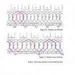
Here’s two diagrams from the tutorial that I’ve color coded to make it easier to see how the windings are connected in lap and wave wound armatures:
armature winding.jpg

In a lap wound armature each coil is connected to adjacent commutator bars. As you proceed around the armature all of the coils are connected in series. In figure 14 note the a coil connects from commutator bar 1 to bar 2; the next coil connects from 2 to 3 and so forth until 12 connects back to one, completing the ring. If you check adjacent bars you should find the same resistance between each pair and it will be a fairly low resistance. If you checked between bars 180 degrees apart you would see a much higher resistance. If a there were an open coil in the armature the resistance between adjacent bars would be much higher that normal.

A wave wound armature has coils that connect directly to the opposing commutator bar (about 180 degrees for one pair of brushes, about 90 degrees for two pairs of brushes, etc.). In figure 17 you can see how the red coil connects from bar 1 to 6. If you follow the circuit around you will find the following connections: 6 to 11; 11 to 5; 5 to 10; 10 to 4; 4 to 9; 9 to 3; 3 to 8; 8 to 2; 2 to 7; and finally 7 connects back to 1. Again all of the coils are connected in series. If you check adjacent commutator bars you will find a fairly high resistance. Since there are an odd number of bars there isn’t a bar at exactly 180 degrees, but the two bars on either side of the split 180 degrees from a given bar are connected by coils; for example, bar 6 is directly opposite the split between bars 1 and 11. Bar 6 connects to bar 1 via the red coil and bar 11 via the blue coil. So you should find a low resistance between a given bar and the two bars on the opposite side of the commutator (if the machine had two sets of brushes you would be looking at 90 degrees).

I think that there’s an error in the tutorial’s version of Figure 17 relating to the brushes. I’ve corrected it in my drawing. Note that in the brush position shown the red and blue coils receive power at the same time, but in opposite polarity.

There lots of variations on the two basic winding schemes and I’m far from an expert. But hopefully the above will help us understand your readings.

Here are a few more links that discuss DC armature winding:

Unfortunately, my machine is sitting in a corner and I don’t have access to check the commutator resistance on my generator. I'll have to leave it to you to figure out what sort of winding we're dealing with.

Checking the exciter’s armature will be similar to that of the generator, although it’s very possible that it’s wound differently. I’m very interested to see what you come up with. You should probably remove the brushes when you’re checking the bar to bar resistances, since the brushes will be shorting out at least on pair of bars.

How many commutator bars do the generator and exciter have?

Cal
 

Attachments

  • armature winding.jpg
    armature winding.jpg
    14.7 KB · Views: 6,551
Last edited:
Had another look at resistances with a calibrated Fluke meter...... Basically no difference.
The armature readings are confusing. Seem to vary between 1 and closer to 10 ohms as you rotate it. And I am still confused as to why I cannot find any open circuits between any of the commutator contacts.

As Cal has pointed out, post 16, you should not see an open circuit between any pair of comutator bars.

Here are three simple tests you may perform to test your armature:

1. Measure the resistance from one commutator bar to the bar 180 degrees opposite to it. Repeat for 1/2 the total number of bars. (In other words, check each pair of bars the same way.) The resistance should be about the same each time.

2. Measure the resistance from one commutator bar to the one adjacent to it. Again, repeat for 1/2 the total number of bars. The resistance should be about the same each time. (Correction: You need to do all pairs, see Cal's post #18 below.)

3. Measure the resistance from each commutator bar to the armature stack (the iron part of the armature around which the coils pass). It should be infinite resistance. There is no connection between the coils and the stack.

If each of these tests gives the expected result your armature is probably electrically OK.

Notes:

A. I am too lazy to run out to the shop and count the number of commutator bars and/or to made these measurements myself. Hence the lack of detail above. Sorry.

B. I am not a smart enough bear to figure this out by myself. I had help from the Internet. See:

How to Check a Motor Armature for Damaged Windings :: Groschopp Blog

Chris
 
Last edited:
Good link. Note that he's talking specifically about lap wound armatures. However, if you do the three tests and get the same values for each test the armature is probably OK. As noted earlier, for the “180° Resistance Test” on an armature with one pair of brushes and an odd number of commutator bars you need to check both bars adjacent to the split directly across from the bar under test.

You can't just check half of the adjacent bars; you need to check each pair.

While you’re at it, look for black bars on the commutator which may indicate a bad winding.

Cal


Back
Top