What's new
What's new

Need Reliance 3 HP stator coil wiring diagram info

bll230

Hot Rolled
Joined
Jun 14, 2007
Location
Las Vegas
The 3HP reliance motor in my wiad 10EE had been refurbed by a motor shop by the previous owner. The shop put in new silicone insulation wire and new bearings. I removed the front end out of curiousity, and the stator coil wires were not what I was expected. I assumed that A1 and A2 would connect to the brushes, F1 and F2 would connect to one coil circuit, and S1 and S2 would connect to another coil circuit. However...

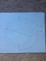
The brushes are in series with the smaller pair of coils, ie, A1 goes to one of the smaller coil terminals then its other terminal goes to the other small coil, then to one brush and the other brush goes to A2. picture 1

The F1 and F2 are connected to the inner connections of the large coils. picture 2

The S1 and S2 are connected to the outer terminals of the large coils. picture 3

Is this right or did the motor shop mess their connections up? The motor seemed to run fine.

IMG_0598.jpgIMG_0599.jpgIMG_0600.jpg
 
I have the WIAD schematic if you want to copy it

But hurry up over my lathe is sold and will be picked up on Saturday

New owner is getting all the paperwork and manual

Rich
 
The 3HP reliance motor in my wiad 10EE had been refurbed by a motor shop by the previous owner. The shop put in new silicone insulation wire and new bearings. I removed the front end out of curiousity, and the stator coil wires were not what I was expected. I assumed that A1 and A2 would connect to the brushes, F1 and F2 would connect to one coil circuit, and S1 and S2 would connect to another coil circuit. However...

The brushes are in series with the smaller pair of coils, ie, A1 goes to one of the smaller coil terminals then its other terminal goes to the other small coil, then to one brush and the other brush goes to A2. picture 1

The F1 and F2 are connected to the inner connections of the large coils. picture 2

The S1 and S2 are connected to the outer terminals of the large coils. picture 3

Is this right or did the motor shop mess their connections up? The motor seemed to run fine.

View attachment 194566View attachment 194567View attachment 194568

May 'run fine', no load. May compensate for load increase in one direction, make it worse in the other.

I have a 'small frame' 3 HP Reliance wired in a similar manner such that only two leads leave the peckerhead to the power source. "Comp" S1, S2 are in series with the A1, A2 leads, which end chosen by preferred direction. Connection info was on the data plate.

That said, this motor had been fitted with a GE tachogenerator, so the PO and I figured it had come out of a DoD, DoD Contractor, or other deep-pockets Big Corp rebuild/upgrade, not an OEM WiaD.

Does your motor still have its nameplate? And if so, can you post a photo of it?

Page Two:

There is a thread here on PM I can go find IF you are NOT using the WiaD hollow-state fire bottles to drive it.

As the comp favours one direction over the other, IF one wants correct-sense of assistance bothways, a FWB can be inserted so it always has the same polarity, even with Armature reversed.

IIRC, one of the posters discovered he'd been running for 'many' years with S1, S2 not even in the circuit at all.

That seems to work better with Solid State Drives, as they regulate faster than the Comp winding, and we don't need them fighting each other over who has the right to do what, with which, and to whom.
 
Here is the data plate. From the connection diagram I assumed there would be two coil circuits, s1-s2 and F1-F2. It is the third coil circuit that is puzzling me. If the motor hadn't been refurbed I wouldn't be questioning the wiring. The dataplate shows the armature being reversed with the series field the same and the shunt field the same for reverse control. Now it looks like there is some tertiary field that is reversed with the brushes.

addition for page two:

The previous user had a cobbled together KB drive system, not the thyratrons. I think I know how to do the DC drive setup correctly. The previous user did not have S1 and S2 connected. Now the mystery deepens. What do you mean by the compensation winding?
 

Attachments

  • IMG_0597.jpg
    IMG_0597.jpg
    93.6 KB · Views: 571
Here is the data plate. From the connection diagram I assumed there would be two coil circuits, s1-s2 and F1-F2. It is the third coil circuit that is puzzling me. If the motor hadn't been refurbed I wouldn't be questioning the wiring. The dataplate shows the armature being reversed with the series field the same and the shunt field the same for reverse control. Now it looks like there is some tertiary field that is reversed with the brushes.

addition for page two:

The previous user had a cobbled together KB drive system, not the thyratrons. I think I know how to do the DC drive setup correctly. The previous user did not have S1 and S2 connected. Now the mystery deepens. What do you mean by the compensation winding?

Good news. Same motor I have, been tested HARD with Eurotherm/Parker-SSD drives.

First, field is field, and +F1 / -F2 are 'the usual' and not involved in the compensation scheme.

Now.. take note that for each 'preferred' direction - the left and right halves - there is a strap or common-tie point shown between one of the Armature windings and one of the Comp or "S" windings. Those were meant to be connected right in the peckerhead box.

With the Field already taken care of, that leaves but two leads to be connected to the DC supply.

The effect of the comp winding being in series with the Armature is that 'assists' as torque demand reduces CEMF and boosts armature current draw.

But only in the 'preferred' direction. When the motor is run the opposite direction, load and increased current draw causes the compensation winding to fight against the Armature instead of helping it.

That was the plan when the motor left Reliance, anyway. It wasn't necessarily expected to carry a load in both directions.

Here are the threads discussing how others on PM dealt with the issue.

http://www.practicalmachinist.com/v...winding-polarity-98457-post309599/#post309599

http://www.practicalmachinist.com/v...larity-continued-99190-post316631/#post316631

http://www.practicalmachinist.com/v...ings-question-272330-post2121315/#post2121315

Note in the third link that ten years had passed, and the OP THEN discovered he had been running all those years with S1 S2 not connected at all.

That still works...

:D

A good explanation and recaps are here:

http://www.practicalmachinist.com/v...ings-question-272330-post2122422/#post2122422

http://www.practicalmachinist.com/v...ings-question-272330-post2122547/#post2122547
 
The third field coils are probably interpoles that reduce brush sparking. The interpoles are usually the smallest and are in series with the armature and are reversed with it. The series fields are to increase the total field strength as load increases. These are always the same polarity because they must keep the same relationship with the shunt field. Their action is similar to the IR Comp function in solid state controllers. I am not familiar with WIADs but the Modulars have current transformers in the incoming power leads that adjust the thyratron firing.

The armature current should go through the interpoles and the brushes, it doesn't matter which order as long as the polarities are correct. The armature current is supplied through the series fields but they are not reversed. The reversing contactors should be between the series fields and the brush/interpole circuit. Reversing the series field with the armature can make the motor do some very strange things. The power to the shunt fields stays the same all the time.

Bill

We have at least two examples of those 'strange things' in PM threads. Poster had the S1,S2 leads connected to favour reverse. Running in forward, when the cutting tool applied a load, RPM started to drop, compensation winding helped it drop further, and faster!

At least on that particular install, the S1,S2 leads were hard-connected, not maintained outside of the contactor reversal system.

For THIS case, as a Solid State Drive is on the menu, no 'DC Panel' or contactors needed, I suggest just taping S1, S2 off.

I'd also suggest, of course, finding a new home for the KB drive where it can earn an honest living at what it was meant to do. Power a 90 VDC or 180 VDC motor AND NOT make a fool of itself nor frustrate its owner in a vain struggle to operate a 230 VDC motor.

:)
 
The small coils in series with the brushes are called interpole coils. They shape the magnetism from the shunt/ series windings to reduce the sparking at the brushes.

They appear to be connected properly.

Bill
 
Thank you very much for the information. I am going to read all the threads that Monarchist listed and ponder all the information. I need to complete some of the mechanical restoration work and get my DC drive in place before I will be actually connecting leads. I will report back when I get it running.

Thanks again.

A bit more 'back burner' pondering material whilst all that is in-train, then.

KB drives are fine for 90/180 VDC motors. I have 'many' of them.

Any revision level of DC 10EE needs more than that. Nominal 230 VDC motors were run where 250 VDC to 270 VDC or even higher were 'available if asked for'.

Under heavy load, or to make stabilization less difficult when in 'Field Weakened' range, that IS 'asked for', even if only briefly.

The sturdy KB, OTOH, can make chips 'normally' only up to about 2/3 of whatever a 230 VDC motor's 'base' RPM might be.

Above that, having had to go 'early' into Field Weakened mode even to hit 'base' RPM, it gets progressively less-capable at delivering torque, and downright abysmal at regulating RPM under load once into the higher-yet Field-Weakened range.

Suggest scouting a Parker-SSD 514C for the Armature, around 6 to 7.5 kVA in transformer, or combinations of transformers to feed it 320 to 340 VAC in - fully-isolated, not 'autotransformer', please, and adding Parker-SSD 507 to supply and control field power.

I'm all ears if you can find a better combo for a DC Drive, but know firsthand a KB is not it.
 
Monarchist, I have been reading about the 514C-16 and it does look like a good choice. The manual seems to indicate that it can use any input up to 480 volts. You mentioned that you have 350 volts and Everetteng has 330 volts; however, there are many 240/480 volt transformers on ebay, far more than intermediate voltages. Is there any problem with using 440 volts and just setting the upper armature voltage as 230 in the 514C?
 
Monarchist, I have been reading about the 514C-16 and it does look like a good choice. The manual seems to indicate that it can use any input up to 480 volts. You mentioned that you have 350 volts and Everetteng has 330 volts; however, there are many 240/480 volt transformers on ebay, far more than intermediate voltages. Is there any problem with using 440 volts and just setting the upper armature voltage as 230 in the 514C?

I could have. I do not.

First:

The closer the max input voltage is to the max DC the greater the 'on' time, and lesser the 'off' time when running fast and hard. That makes for a smoother-running system, as the ripple filter and motor windings do not have to work as hard to integrate the pulsed DC back in the direction of pure or 'rotating power' DC. SCR drives are rough as a cob under light load - very long 'off' time, very short 'on' time.

Second:

OLDER SSD drives, same model, earlier 'Revision', did not carry the full 480 VAC 'working' rating. So if you seek a used one, you might be out of its bounds.

And finally, it is always better to have a bit of headspace, not push the limits. Spikes exists - line side as well as load.

A 1:1 220/230/240 primary and secondary, plus a 2:1 step-down, 220/230/240 primary, 110/115/120 secondary, arranged primaries in parallel, secondaries in series, will give you a max of around 360 - 400 VAC, and that is about as high as I would want to go.

The 'sweet spot' is around 320 VAC, as Mark has.

My 349 VAC nominal?

Well.. I make tests, not chips, and still have a few more limits to push...

:)


Back
Top