peterh5322
Diamond
- Joined
- Dec 15, 2002
- Location
- Monterey Bay, California
Forum member DaveE907 contributes this excellent narrative and photos album detailing the making of replacement knobs for his 10EE.
The text and photos are Dave's. The photo album is necessarily split across multiple posts.
After assessing the poor condition of the original zinc alloy knobs on my 1952 Square Dial 10EE I decided to make a new set of thirteen. There are lots of ways to make them, this is how I made my set.
I chose stainless steel to avoid and to ease machining used 303. In order to reduce cost and utilize material I had on hand they were made as two piece assemblies, a knob and a shank joined with high strength Loctite retaining compound. That way a 12 in. length of 2.0 round 303 bar on hand would be sufficient to make the entire set when coupled with about 18 in. of 1.25 round 303 bar.
Among the thirteen knobs are seven distinct variations. The first step was to measure them all and design their replacements. Of the thirteen, seven are identical and the remaining six are all individual designs in some respect. The only common dimensional features are knob OD, face profile and knurling pattern. All other characteristics vary. A chart of features was made and design sketches were made of the seven varieties.
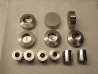
My process was to make all the shanks to OD, length and finished bore (except for the .750 through bore for the upper left gearbox knob, it was rough bored undersize). The knob bodies were blind bored for .001-.002 clearance with their shanks (there are three different shank diameters) and turned the correct back angle taper for that particular knob. They were left at the 2.0 bar diameter and sawn off to the correct length for that knob leaving enough length for cleanup on the face.
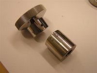
Photo 1 shows some of them before bonding, and Photo 2 shows one shank and knob body bonded with the Loctite compound used to assemble them.
The face profile was designed as a 4.00 in. radius and they were produced by step turning.
Photo 3 shows the shop calculations made to produce the contour with .005 in. moves of the carriage. I like to make a chart with direct carriage positions and crossfeed dial numbers to make it fast and easy to machine the parts.
The chart I used is Photo 4.
Photo 5 shows the step turning operation, each knob face took about three minutes to turn. The knob 1.965 in. OD was then turned and the corners chamfered .020x45º.
Photo 6 shows most of the knobs after the faces and OD were turned.
The knob face profiles were worked on a 1x42 in. belt sander while being spun at 3600 rpm on an arbor in an electric hand drill. Just enough was removed to bring the surface to where the steps just disappear with a 180 grit belt. Both the backed up and flexible portions of the belt are useful and very good results were achieved. Surface finish was then refined on 220 grit and 320 grit belts, 320 was the finest grit I had on hand.
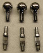
Photo 7 shows six knobs after working them on the belt sander. Each one took about 3 minutes to reach this stage.
Photo 8 shows twelve of them after the belt sanding process and ready for final polishing.
Now the knob with the .750 dia. through bore was drilled through the knob face and the bore was finished to size.
They were polished while being spun with the same hand drill at 3600 rpm. The shank OD, back taper and face were polished, the OD was not. 320, 400 and 600 grit with honing oil followed by Flitz polish made quick work of them.
Next they were knurled by cutting 160 90º notches .020 in. deep in the OD of the knob with a .375 dia. four flute end mill.
Photo 9 shows the shop calculations made to position the cutter to properly cut the notches. 160 notches was chosen as a close approximation to the original knurl pitch and also to be easy and fast to do with a 40:1 dividing head. Each move is one quarter turn.
Photo 10 shows the setup with a HSS end mill on the first part, I switched to carbide to speed things up on the rest of the knobs. Each knob took 9-10 minutes so each notch was cut in under 4 seconds. It was good exercise!
Photo 11 shows twelve of the completed knobs (except for engraving on those that require it) ready to be fit to their mating parts.
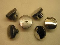
Photo 12 shows some of the old ones compared with their replacements.
They're a great improvement and feel good in the hand.
The text and photos are Dave's. The photo album is necessarily split across multiple posts.
After assessing the poor condition of the original zinc alloy knobs on my 1952 Square Dial 10EE I decided to make a new set of thirteen. There are lots of ways to make them, this is how I made my set.
I chose stainless steel to avoid and to ease machining used 303. In order to reduce cost and utilize material I had on hand they were made as two piece assemblies, a knob and a shank joined with high strength Loctite retaining compound. That way a 12 in. length of 2.0 round 303 bar on hand would be sufficient to make the entire set when coupled with about 18 in. of 1.25 round 303 bar.
Among the thirteen knobs are seven distinct variations. The first step was to measure them all and design their replacements. Of the thirteen, seven are identical and the remaining six are all individual designs in some respect. The only common dimensional features are knob OD, face profile and knurling pattern. All other characteristics vary. A chart of features was made and design sketches were made of the seven varieties.
My process was to make all the shanks to OD, length and finished bore (except for the .750 through bore for the upper left gearbox knob, it was rough bored undersize). The knob bodies were blind bored for .001-.002 clearance with their shanks (there are three different shank diameters) and turned the correct back angle taper for that particular knob. They were left at the 2.0 bar diameter and sawn off to the correct length for that knob leaving enough length for cleanup on the face.
Photo 1 shows some of them before bonding, and Photo 2 shows one shank and knob body bonded with the Loctite compound used to assemble them.
The face profile was designed as a 4.00 in. radius and they were produced by step turning.
Photo 3 shows the shop calculations made to produce the contour with .005 in. moves of the carriage. I like to make a chart with direct carriage positions and crossfeed dial numbers to make it fast and easy to machine the parts.
The chart I used is Photo 4.
Photo 5 shows the step turning operation, each knob face took about three minutes to turn. The knob 1.965 in. OD was then turned and the corners chamfered .020x45º.
Photo 6 shows most of the knobs after the faces and OD were turned.
The knob face profiles were worked on a 1x42 in. belt sander while being spun at 3600 rpm on an arbor in an electric hand drill. Just enough was removed to bring the surface to where the steps just disappear with a 180 grit belt. Both the backed up and flexible portions of the belt are useful and very good results were achieved. Surface finish was then refined on 220 grit and 320 grit belts, 320 was the finest grit I had on hand.
Photo 7 shows six knobs after working them on the belt sander. Each one took about 3 minutes to reach this stage.
Photo 8 shows twelve of them after the belt sanding process and ready for final polishing.
Now the knob with the .750 dia. through bore was drilled through the knob face and the bore was finished to size.
They were polished while being spun with the same hand drill at 3600 rpm. The shank OD, back taper and face were polished, the OD was not. 320, 400 and 600 grit with honing oil followed by Flitz polish made quick work of them.
Next they were knurled by cutting 160 90º notches .020 in. deep in the OD of the knob with a .375 dia. four flute end mill.
Photo 9 shows the shop calculations made to position the cutter to properly cut the notches. 160 notches was chosen as a close approximation to the original knurl pitch and also to be easy and fast to do with a 40:1 dividing head. Each move is one quarter turn.
Photo 10 shows the setup with a HSS end mill on the first part, I switched to carbide to speed things up on the rest of the knobs. Each knob took 9-10 minutes so each notch was cut in under 4 seconds. It was good exercise!
Photo 11 shows twelve of the completed knobs (except for engraving on those that require it) ready to be fit to their mating parts.
Photo 12 shows some of the old ones compared with their replacements.
They're a great improvement and feel good in the hand.