What's new
What's new

New toy (project) Series 61 @ 13x30

matt_isserstedt

Diamond
Joined
Dec 15, 2003
Location
suburbs of Ann Arbor, MI, USA
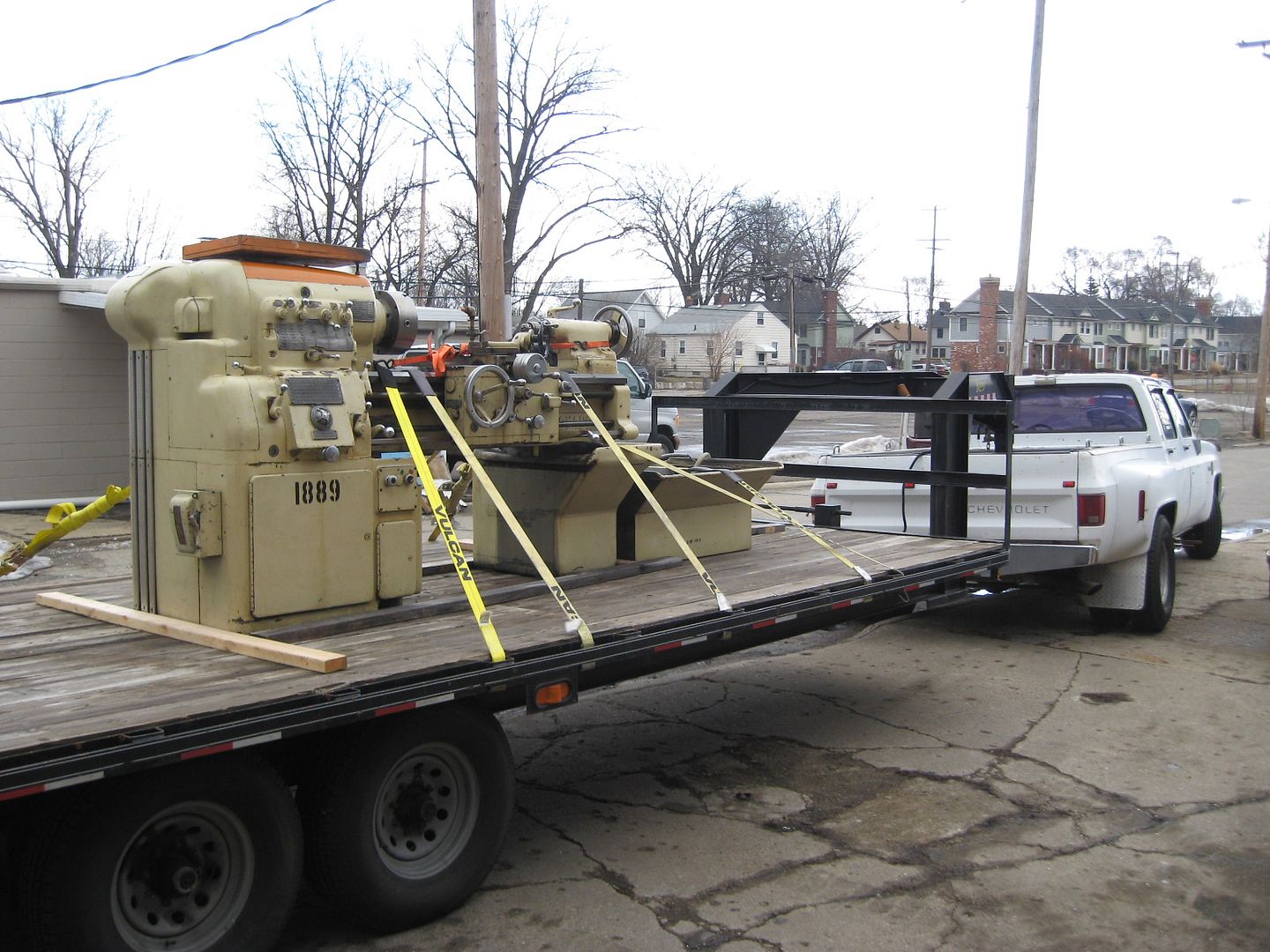
So I picked this up earlier today, I had the nice experience of meeting PM Member USMachine and tell some stories of hauling iron :)


Now I have a dilemma. I already have a CK 12x30 with good bed & tight cross slide, however wonky clutch and really crusty old peeling paint and nearly every bit of chrome is surface rusted just due to the way the former owner stored it. Around a 500rpm top speed machine although I realize that could be changed higher.

And I have this, looks great, smooth in all speeds, higher top speed, tight cross slide but some bed wear in the center. The flat tailstock way is touching the saddle near the center, climbs around .005" on a dial indicator once contact is established. Just a WAG without using any other alignment tools, that .010" to .015" or so would be needed to cleanup fully. While I respect the CK of course, the 61 is the white whale I've been chasing. Something about those cast iron covers...

Unfortunately I can keep only one of the two long-term, so I have to formulate my decision process. Rebuilding a lathe is also a goal of mine, personally, just to go thru the steps and train myself further and hopefully come out better than before.

Hoping to attend Richard King's scraping and rebuilding class if enough students apply (think 3 more needed to fill it out) in April, so that sounded like the possible entry into a big project to refresh it.

I've read the stories of Commerce (way) Grinding, was hoping someone had experience with someone in SE Michigan for same type of service, just so I can get some quotes for about what I'm going to get into. Or maybe you want to talk me out of it :) Does Monarch in Sidney grind beds there or is it only available to a full-service refresh (I know enough I don't have to ask the price for that...not that I don't respect them, just out of reach currently.)

Thanks for ideas and input.
 
This probably isn't the advice you want. Personally I would keep em both, use the ck as a project to restore, and use the 61 in the meantime. Once both are running I would probably put a 3 jaw on one, and 4 jaw on the other and use em. Nice lathes!
 
This was one of the stranger machines I've moved. At first glance, the carriage is setup perfectly for using a forklift under the bed (it doesn't hang down in the way), so big plus there. It looks like you just drive right up, pick it up, and move carefully from there. However the CG of the machine is literally right under the chuck. The left fork, as close as I could get to the headstock, still wouldn't balance with the carriage all the way to the right and the tailstock clamped with half of it hanging off the end. My thought was that with all the load (almost 5k) going on the left fork, it was deflecting to the point that it was making the balance worse.

So I used a thinner wood hardwood block, about 1/2" thick under the left fork, to create sort of an artificial tilt right-left to compensate for the deflection. That was perfect and no more sweating. The forks are still in good condition, Im happy to report. When moving, I got 10k rated forks for my 7k lift but that decision has been a good one several times over.
 
Learned something from the last rigger I used. On a short bed lathe, such as you're discussing, besides the 2 X 4's on the forks to provide clearance for the forks under the clutch and feed rod, he used a short chain to tie the fork to the bed between the bed ways. Worked great.
Harry
 
I think its 5hp, 1000rpm plated speeds. Its serial #36000 which is kind of interesting.

One thing Doug (USMachine) and I talked about, was the possibility of disassembling the saddle, and relieving the land underneath which is now touching on the tailstock way. I've let the idea sink in for a few days, it seems very reasonable, after all it should be clearance under to the tailstock way anyway, slightly more won't hurt anything even if I had a full refresh someday, and I could probably use the machine in some integer number of years shorter time span with a lot less disassembly than a full rebuild project...which I can see is going to take about a half acre of garage space :D With the saddle off I could also check a little bit with a 4' master straightedge that I have and do a few spot and feeler gauge checks to quantify a little better.

I just had the end gearing cover off tonight, that's one of the most impressive things I've ever seen on a manual lathe, I've seen it before on the 16" I owned previously and sold, but it continues to impress me every time. It obviously works as the gears look brand new.

Does anyone know if these models had metric change gear sets as an option? Just curious :)
 
Got a ballpark quote from Advance Precision Grinding in Roseville, MI for $500-600 to regrind the bedway, 1-2week turnaround, I estimated .010" needed to be removed. I'd drive over just to check out their shop before committing to it but just thought I'd add for future reference. I saw Solon Grinding mentioned in earlier PM threads but google also directed me to "solon grinding auction" as they seem to be inop now.
 
I didn't inquire about the saddle etc yet. The cross slide actually seems pretty good, it may have had a "top end rebuild" along the way as I can see flaking on the cross slide a fair ways in and the screw is very low backlash.

Relative to the inverted V and flat of the saddle I was actually thinking that it might be a perfect job for the Putnam planer in my shop. Of course compounding the completion time is the planer doesn't have a reversing table drive system at present....maybe this would up my 'round Tuit quotient slightly.

I was a little worried about picking up unworn OEM datum surfaces under the saddle but my thinking is those are present in the machining for the apron interface, and possibly also on the rear taper attachment surface as well (this one doensn't have a TA).
 
Got a ballpark quote from Advance Precision Grinding in Roseville, MI for $500-600 to regrind the bedway, 1-2week turnaround, I estimated .010" needed to be removed. I'd drive over just to check out their shop before committing to it but just thought I'd add for future reference. I saw Solon Grinding mentioned in earlier PM threads but google also directed me to "solon grinding auction" as they seem to be inop now.

Matt,

Did you talk to Scott at Monarch?
Last time I talked to them they were using someone in Roseville, MI.

Let us know who you end up using.
BTW love the Model 61, does yours have the lead screw reverse?

Kevin
 
Matt,
If the carriage is interfering with the tailstock ways, I'll bet you a coffee and donut that the carriage is worn equal or more than the bed.
I had a similar situation with my Hendey T&G.
Check out post 127 on my wreck thread to see how I finally figured out where mine stood.
http://www.practicalmachinist.com/vb/monarch-lathes/hendey-9-t-g-wreck-216732/

Not wanting to be "Job's Comforter", but beware of the quick fix... It'l take you a lot longer than you think. Every screw or bolt you turn will reveal something else to fix. I'm nearly 4 years into mine and not done yet!

Pete

BTW, Love that 13x30!!
 
I will check in with Monarch-Sidney to see if they have any tips. Thanks for a good check, Pete, I figure at minimum I need extra space for at least 2 sheets of 4x8 plywood to hold parts in various states of disassembly/reassembly/inspection, and enough room to roll my gantry around. The headstock is heavier than the transmission in my 1 ton truck!!

I did figure out metric change gears are an optional accessory, the manual I had for the 16" has all the components for the 13-16-20 family.

My head is working on a copy of the KingWay jig, using the 199Z level as a feedback device. I think that's a necessity to at least do a survey.
 
Some picture info on how to disassemble, for future reference.

The weather got warm, I got excited and rolled up the garage doors to work in this newfound thing called sun :)

There are in this lathe 3 shafts to remove (4 if power rapid traverse is fitted). They all share a common end block, nothing exotic there just plain bronze bearings. However I was a little worried about underlying dowel pins. The Monarch documentation is excellent at showing the "explosion" of all the components but no fasteners are depicted.

So the end block has two 1/2"-13 socket head screws holding it in, no mystery there.


A little tapping with a deadblow mallet and the block slid right off the end. There are no dowel pins, just a machined "ledge" which holds the vertical position of the block.


So that was easy, now to extract the 3 shafts.

The top, leadscrew, has a keyed gear bolted to the end, per the manual, so I attempted to extract the cast bearing holder from the end of the thread & feed box. There are 4 socket screws, the 4th, rearmost one looks impossible to get, but then you can see the designers provided an exact space between the intersection of all the castings and V-way for a standard sized allen wrench to fit and make 1/6 of a turn. A little slow, but brilliant.


I used a screwdriver for gentle prying between the two cast flanges to rotate the upper one slightly and break the years of paint and crud loose.


Here is what you see when the cast flange is removed.


And the gear which must be removed.


A single hook spanner wrench and a strap wrench are ideal. The strap wrench is MIA from the toolbox, so I elected to go with channellock and rag protection. There is a bearing-nut retaining-washer which has to have one of the teeth folded back out of the slot.


Once you remove the nut, the gear is keyed, the key drops out and the double roller bearing package slides off the shaft. It has a central spacer tube to keep the inner races out of a bind with the outer races, as this is also used for thrust control.
 
Here is the leadscrew after the other components are removed and bagged.


You can sort of see down the bearing block the open single row roller bearings and the spacer. Sorry for poor focus. For now its going in a bag as there don't seem to be obvious problems.


I did find that the threading dial must be removed. The internal gear won't interface with the non-threaded portion of the shaft. A possible ominous clue here, two of the three bolts holding in the threading dial were previously removed, my guess is so the threading dial could pivot down slightly and reduce binding with the top of the thread crests (IOW from the saddle/bed wear combination dropping the saddle, and apron down)


Feed rod is a little easier. Two chances at removing a tapered pin, I only needed one :) Usual care to gauge each end with a caliper to find the small end, and then not hammer directly on the pin itself, instead use a flat pin punch. One removed, the thread rod drops out smoothly to the side. I did note some play apparently in the keyed transition to the apron when I rotated the shaft by hand in either direction. So I will have to take a closer look there.


Last shaft is the clutch shaft. Two tapered pins thru the body of the lever arm. However...there is no room underneath to swing a hammer nor line up a pin punch. So I went to the back of the lathe, and removed the rocker lever/yoke linkage which transitions up to the clutch. I removed upper and lower lever arms although only the lower one is required. Single setscrew and a woodruff key. All seems reasonably tight.


View looking down toward the ground of the complete exterior linkage.


Once the linkage is freed in the back, the front control handle can be lifted all the way up to the point needed to remove the tapered pin.


Freed. The taper pin also secures a round-OD/square-ID bushing, so I left it in the orientation and put back the pin for now.


I did notice some wear (IOW lost motion) on the same bushing on the end of the apron control handle. Another note for future.

That's all for right now until I get some more time to work...
 
Monarch offers(ed) metric change gears, the manual should have a parts page. I chose to make my own for the 16" Series 60 I had. It's close to the end of the "Another New Toy" sticky.
Harry
 
Matt, Im interested to see what you come up with on the grind shop, I recently picked up a 30" 10EE that Id like to bring back to life, and Roseville wouldnt be a bad drive.
 
I started dropping down the apron today, holding off on full removal pending clearing some more bench space. I loosened the socket head screws about 1/16" and dropped the apron until I could just see daylight. Does anyone know if there is an actual lube line (copper tube) connecting the two? Or is it a face-seal o-ring that's entrapped between the saddle and apron passages? I don't want to have a 90lb assembly in one hand hanging by a copper tube, that's bound to end poorly....

My backup plan was to get a couple of longer 1/2-13 socket heads so I can drop it down, controllably, in stages and still have it hanging by at least two bolts for support.

I haven't talked with Bill at Advance Precision Grinding any further, I would like to do some more checks under the saddle, and on the bed with a master straightedge, and with a Kingway-like jig to see what I'm up against.

I did some study on Moglice, it seems interesting and good for really severe wear, although admonitions about it being a miracle fix abound. Re-doing the cast iron seems preferable if there's enough left, I then have to study how the power transmission elements can be realigned to match. The end block supporting the 3 horizontal rods seems easiest....simply mill the ledge on the casting, possible oversize on the bolt holes.


Back
Top