jpevner
Stainless
- Joined
- Apr 5, 2005
- Location
- Central MA
Folk;
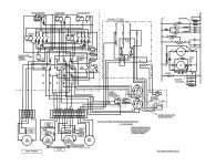
I have spent some time scanning and copying the schematic from the plate of my DC cover panel. It was very darkened and oily, so I traced it in Open Office, and converted to .pdf, also, I have a jpg. (not as high quality). As soon as I figure out the attachment limits, I will try to get this going.
Notes:
My lathe is a ELSR, so if yours isn't, the switchbox labeled "micro-switch LSR housing" is replaced by your forward-reverse drum switch.
There were several variants and engineering changes in the history of the M-G. We can add variant docs, or notes, whatever is needed. My unit is '43.
If there are errors, please let me know. Some parts of the label were close to illegible.
Enjoy, and regards,
Jon P.
p.s. The .jpg is up, the pdf will have to be homed at my webpage, unless someone can make an exception and lift the limit to about 120k. Currently the limit is about 19k. I will try to get the .pdf up after dinner.
Attachments
Last edited: