What's new
What's new

Shareing some pics of my VFD and gearbox conversion

Tipsy

Aluminum
Joined
Nov 15, 2005
Location
Topanga CA
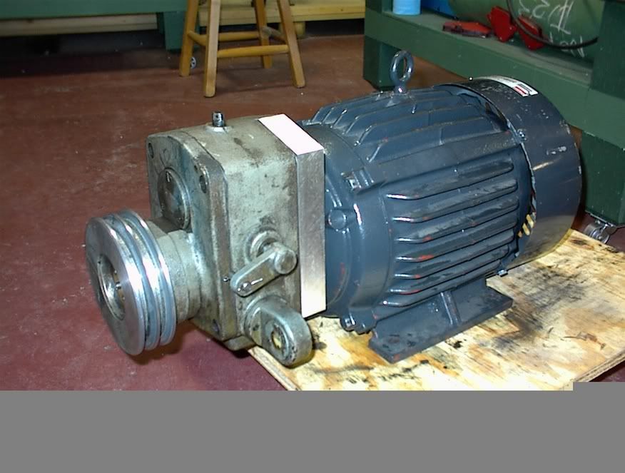
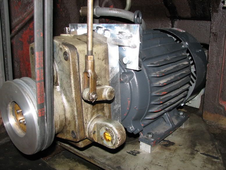
Thanks to some pictures of previous posts, I was able to adapt a new 10hp inverter ac motor with and SJ200 VFD, to the original back gear. Amazeingly it works! I will next try to post a few pictures and descriptions.

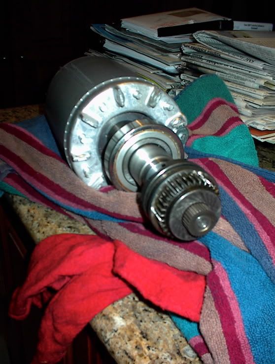
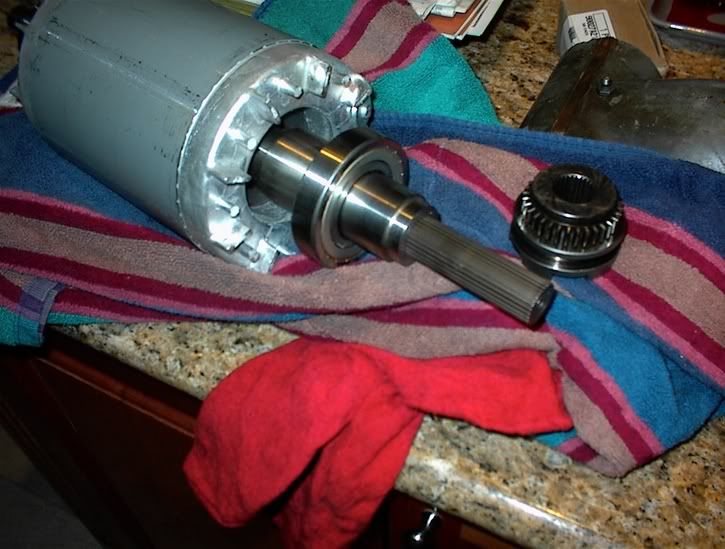
Below is the new motor shaft with a new spine added. I cut down the shaft to 0.5 inches, made a molly ring and used an EDM to cut the splines. The shaft was frozen, spline heated and pressed togeather really quickly--it will never come apart again.
DSC00003_1.jpg
 
Too bad that the motor face was not a c-face type. As an only option, I milled the front motor houseing flat, around the front bearing. The makeshift c-face was then onlt about 4in diameter around the shaft. I then used three cast tabs on the front motor bell houseing, to tap three holes which the aluminum adaptor plate bolts to. Then the back gear bolts to the adapter. Allignment was critical since the mesh is determined by this step.

Below you see the motor, 1.25 inch thick adaptor and then the back gear. I decided the the mini-c-face was too small to permanently hold perfect allignment so later pictures show additional welded aluminum brackets between the outside of the adaptor plate, and the bolts that hold the motor bell houseing onto the motor body.
2aeba1f6.jpg
 
Lastly, the finnal set up. The center height was only 1 inch lower, which required some machined spacers under the motor.

Almost perfect fit within the confined space of a 10ee.

Features of a motor that seem to make a simpler retrofit; a longer than original shaft (orig 2.75, my new motor was about 3.75+. Secondly, a c-face style motor makes for a rigid union without additonal brackets.

So far, the thing runs great, seems like huge torqe even in direct drive down to the current slowest speed of 50-75rpm. I really doubt that 10hp is needed, and may be more that the backgear can handle long term, but this is just a hobby, doubt it will ever matter.

This was my first metal working project besides rebuilding my tired Bridgeport. And no I don't have my own EDM, had to enlist the help of a friend for that.

I posted this in the hope that it will add to the amazeing resource that this forum has provided.

IMG_0015.jpg
 
"Secondly, a c-face style motor makes for a rigid union without additonal brackets"

Of course, a C-face motor is always the first choice.

However, lacking that, a relatively thick adapter plate, such as you've contructed, with a "strut" firmly anchored into that plate, and run directly back to the "eye" bolt which is found on most motors of this size, and secured to the motor using an "eye" bolt with a longer shank, should provide the additional support required with the minimum of added complexity.

Incidentally, there are C-face motors with J-type shafts, as for pumps, which shafts are larger in dia. than normal C or non-C motors, and are extra long as well. Could easily be turned down and keyed or splined, with no need for a shaft extension or other half-shaft :) adaptations.
 
"Think you used enough horsepower there, Butch?" (mangled movie reference).

Looks like a nice job. 10HP shouldn't even need the backgear, but with it you can really reduce the speed without seeing any cogging.
 
This was my first metal working project besides rebuilding my tired Bridgeport.
Quite a first project... do you design rocketships for a living or what? :D

Nice job, thanks for sharing.
 
Looks nice.I think you have way plenty HP.Tim Allen??Is that you? :D It is fun to see how each person has designed their adaptor.All the same outcome but by a slightly different way.
 
"It is fun to see how each person has designed their adaptor.All the same outcome but by a slightly different way."

Partly because nearly every 10EE is unique.

Some have a plate solidly bolted to the base, others have a platform riding above the base.

Some have a keyway shaft, others have a spline shaft.

Some have a backgear which is mounted to the base, others have a backgear which is completely supported by the motor's end bell.

The possible variations in starting points are truly quite numerous.
 
Tipsy,
Do I understand correctly that all the torque of the 10-HP motor gets transmitted through the 1/2" diameter section of the original motor shaft? Sounds iffy.
Rich
 
RKLOP,

Yes, the motor shaft is turned down to 1/2 inch, but then the splined collar with an approx 1inch OD is press fit over the shaft with differential temps. The collar backes into a shoulder where the motor shaft changes diameter. You would be surprised by the strength. No way the collar will ever come off, the combination acts like a single unit.

Thank you for the nice coments. I would not have tried the project without the previous posts for inspiration and ideas.

Charles
 
Jeff.How are you changing the motor speed?Sorry if it is shown but I looked at a couple pics and didnt see it.My dial up is so slow I usually pass on most pics if they take too long to load.Just courious.
Jim
 
Jim King says:
Jeff.How are you changing the motor speed?
Jim, I'm using a Teco/Westinghouse VFD that is not shown in any of the pics. I have it mounted on a pod (inch and a half black pipe) that stands behind the lathe on the left side. I can run the lathe up to 2500 rpm - the fastest speed on the tach with this unit very nicely. Since moving out West, I still don't have it hooked up yet. I'll post pics when its up and running.


Jeff


Back
Top