What's new
What's new

Springfield model 70 AKA 1000EE

I went and picked up the CL model 70 in Springfield, the trip was not without incident. I lost a wheel and destroyed a spindle on my trailer. Before I ever got going I had serious doubts about the forklift they used to load it.

The lathe is very heavy; my guess is well over 10K. I used my 20K forklift and it strained to lift it at the end of the forks.

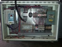
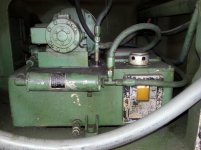
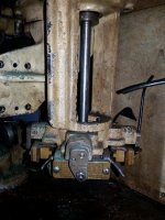
They powered the lathe up and I ran it so it works sorta! The motor is a 10HP 1160RPM motor, with the spindle in open belt it will make just over 1200RPM at 88 Hz. The pulley on the motor is rather small in relation to the spindle? It has AC motors for the rapids, spindle, hydraulic pump and coolant. There is a small plc that is used to delay the spindle until it is in the high range or low range and times out the rapids motor at a preselected time. The leadscrew reverse functions and, as noted above the spindle has two ranges, low is zero speed to about 250RPM, going to a bigger motor pulley may be what is needed ? The spindle control panel is all reworked for the PLC and VFD, there is a pot to set speed, two buttons for high and low range, a button for the rapids and, a joystick for spindle rotation and start.

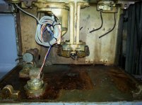
I have tons of questions for anyone with a 13EE-1000EE- Model 70 or 71 regarding what is here and what is missing, the spindle motor of course and the rapids motors. The rapids don't seem to be as rapid as my series 62 and that has a bicycle chain drive that could be tweaked. The constant surface dial is still on the apron but it is not connected to anything, the only guy in the shop who knew anything said it never worked while still DC. The gent who knew the machine told me the lathe was at an electric motor shop of all places when this shop got it. The former owner of this shop did the conversion, they do automation so the level of work is quite good albeit out of sync with the original speeds. The installation of motors, controls and, adapters is first rate, they perhaps just used what was laying around. The former owner was a wheeler dealer from what they tell me. The parts and pieces look like they were all scavenged from other projects?

I will post some pics in the morning, it has been a long day!!

Steve
 
This is pretty cool, someone actually has one of these on the forum :)

Not sure what kind of hauling rig you have, 10k is about the limit on my setup, and hauling at that tonnage makes me want to promise myself its the last trip at that weight. I've blown out tires before, that's also not fun although losing a spindle/bearing sounds less fun. Does the lathe have the standard Monarch plate with the actual weight inscribed?

Back to the CSS setup, I think integrating that with the VFD is entirely possible. Simple would be a regular potentiometer but those don't exactly ramp up over several revolutions. I think you might have to use an encoder or pulsed wheel (ala prox reading gear teeth) and then use a counter function in the PLC to compute and assign a moving Hz value to the VFD. Although that might take some advanced communications like RS485, and the PLC/VFD may not have those functions. It would be very helpful if you could "go online" with the PLC to check out the logic and understand how the designers made it work (plus you can make changes) :D It is nice when you have good electrical work and not hacked up junk. I'm wondering if they had an "as built" electrical drawing to go with it? That would save a lot of time...

Looking forward to the pics!
 
That is one SERIOUSLY attractive lathe, as lathes go, and, by now, most of us on this Forum have come to appreciate the esthetics of the "Monarch of Sidney".

I agree that PLC support can most probably will give you CSS.

Regarding the maximum open belt spindle speed, DO remember that these machines were ... sub rosa ... intended to turn components for https://en.wikipedia.org/wiki/Swan_(nuclear_explosive) and related nuclear devices, which have an operational envelope of most component parts in the neighborhood of 12" in diameter and 24" in length, tapering towards zero at the endpoints.

Experiments which UC's labs (LANL, LLNL, LBNL) executed in the 1950s proved that nuclear devices which were 12" x 24" always worked, and always produced their design yield, and that is really what it is all about, and that these turning machines were almost certainly designed with those specifications in mind.

IOW, while a 10EE was designed for almost any reasonable toolroom duty, as we (the Allies) were just embarking on what would eventually become WW-II, during the end of the Machine Age, and we needed LOTS of tools for the manufacturing of war materiel, the EE1000 was designed for almost any reasonable nuclear duty, as we (the US) were just embarking on what would eventually come to be called the Cold War, the beginning of the Nuclear Age.

A design, of whatever type, which cannot be economically produced, is no good design at all, and these specialized machines were almost certainly designed for a particular strategic objective, whether it was (eventually) winning WW-II, or (eventually) winning the Cold War.
 
Here are some more photos, I would like to hear from others with 13ee or 1000EE's on the hydraulic block. I will post a photo of the motor pulley and would like some feedback on that as well.

Steve
 

Attachments

  • 20140412_163931.jpg
    20140412_163931.jpg
    92.4 KB · Views: 380
  • 20140412_165921.jpg
    20140412_165921.jpg
    96.9 KB · Views: 338
  • 20140412_170019.jpg
    20140412_170019.jpg
    91.1 KB · Views: 385
  • 20140412_170045.jpg
    20140412_170045.jpg
    97 KB · Views: 311
Wow, sorry I am all over your thread trying to get other owners' opinions :)

The hydraulic block is a simple spool based system. The directional valves shift a spool internally to make the fluid flow. Typically there is a pressure and drain/tank line that's common to both functions. The other two hoses go out to the cylinder (etc). If you can't electrically fire the spool usually if you depress the center of the black ring you will manually shift the spool and then, with the pump running, you can see what's actually happening.

Can I guess the tailstock is hydraulically clamped? :) Not really sure what else one would use the hydraulics for (? gear shifting, clamp the saddle, ?)

Its interesting to see the large cable bundle going thru the two pulleys out to the operator control panel. That's an earlier iteration of PLC, the ones of today could use networked I/O and with a block inside the control panel, all the I/O could basically be run with a single 4 conductor cable on something like DeviceNet, or my personally most disliked = ProfiBus. With a possible exception of a backup 24dvc power supply depending on how much current the outputs require.

That's a sweet machine...I want one :D


Matt,

I am not unaware of the function of the hydraulic block, I think it looks too new to be vintage 1955. The headstock has a high and low range shifted hydraulically with these but, no hyd tailstock. There are lines running to the manifold block you see with the hyd tailstock. In looking at older posts about 13EE's 1000EE's and model 70's I saw Peter H say that the 13EE was last made in early 1955, this lathe has a 1-55 build date. Is this a 13EE or a model 70? Is a model 70 a 13EE without the hydraulic tailstock?

Steve
 
I have the brochure for the 1000EE. Brochure says"
The Monarch Series EE PRECISION LATHE
Model 1000
The only lathe of its class in the world

I will get it scanned in the next few days and I can send you a copy (one page is a fold out and the scanner I have access to is not friendly for that).
Also have a brochure and parts catalog for Mona-Matic models - anyone ever seen or heard of these? Headstock is EE ish style - description is "an "air-gage tracer" controlled, automatic cycle production machine for single point metal turning.

Another marketing item is a fold out brochure for the model 80 and 90 - Monarch art deco styling on some seriously big machines. Will need to bring that somewhere to get a scan made.

Paul
 
I just talked to Monarch; this is a 13EE originally sold to ARO tool.

I finally got the headstock cover off, some one glued to down!!! There is an interesting switch array that is all disconnected with gears with cams sequenced to it?

Steve
 

Attachments

  • 20140414_100152.jpg
    20140414_100152.jpg
    97.7 KB · Views: 375
  • 20140414_100301.jpg
    20140414_100301.jpg
    95.4 KB · Views: 366
  • 20140414_100129.jpg
    20140414_100129.jpg
    95.9 KB · Views: 340
  • 20140414_100223.jpg
    20140414_100223.jpg
    97.3 KB · Views: 358
Yep, looks very similar to the 1000EE I ran. Had a few great conversations with the folks in Sidney (15 min from my in-laws) about that lathe. It was a 52' if I remember correctly. The owner bought it from an Air Force base in the 90's. There should be pictures here somewhere. My icon is from that lathe.

My friend and co-worker got dibs on it at the auction. However he has told me it is mine when he closes his shop. Until then I have the pleasure of using it when I need it.

Monarch can provide you with the original electrical specifications.
 
I have been looking things over a bit, the hydraulic shifter is blocked on one rail by a prox switch and an immobilizer bar. This should have three geared speed ranges and as of now only one and open belt. I am waiting for the manual to arrive, I called John AKA Tannewitz hoping he had access to his machines, no luck. I tried contacting Matt AKA 45-70 and user 1000EE with no success.

In addition to the two missing speed ranges the feed gear box is making a bit of noise in high range. There is also a vibration in open belt at about 900 RPM. The paint is a typical "Krylon overhaul" every screw and all the sight glasses were filled with paint. The "rebuilder" used blue silicone on all the covers to the extent that I was afraid they were going to break. The casting are all rough with no filler and look like hell. This is too special a machine to leave half assed; so it will get mechanically fixed now and cosmetically fixed in the near future.

One thing I am still wondering about is the present motor. This is a 10 HP 1160 RPM motor; to get the spindle to its rated top speed 2000 RPM the motor will need to be run at about 145Hz. Should I look at a 1750~1800 RPM motor. In back gear the motor is at 20Hz at 7~8 RPM. The gear reduction is so low that right now at the set max 88Hz the spindle is doing 200 RPM. I am not displeased with the motor but, I wonder if it will work at 2500+ RPM? The only data point I have is that "most" 6 pole motors can do 3600 RPM without damage. 10+ HP three phase motors are cheap as many know, now is the time to act IF the motor is not a good fit.

I also want to try and figure out if the CSS feature can be restored. The large meter under the tach was wired to a small pot on the range selector knob, this set the starting surface feet value. The housing above the halfnut lever had a pot geared to a dial and then geared to a shaft that turned with the cross slide. This housing has only the idler gear and dial remaining. I do plan on installing a DRO and somebody pondered using that to drive a CSS feature, that would be the most straight forward perhaps?

The overall condition of the bed, saddle and mechanical parts is remarkably good and this really favors doing it up right. The AC spindle drive and other systems seem to be OK and while I want to retain original appearance, I am not crazy enough to want to do a original restoration. The controls will need to be redone to a bit more period correct specs and I may try and install the electronics in the base.

Hopefully the manual will reveal the secrets of the 13EE?

Steve
 
I got the manual from Monarch and it is less than I had hoped, the manual conflicts with what I have in several areas and, it has no detail on the stuff that is gone. The manual notes a motor that is used to select gear ranges in the headstock. There is not much on the whys and whats of the shifting either hydraulic or electric. I would really like somebody with a 13EE, 1000EE or Model 70 to take some detail pics of the shift rails and perhaps some specs on the gear changing motor. The spindle motor that is in there now has a dead spot from about 200-400 rpm on the spindle due to the motor base speed and the belting. The rapids drive also seems slow in comparison to my series 62 rapid speed.

Having a lathe that has been changed substantially from original with no good idea of what is right or wrong makes the job much harder. Pictures,literature, first hand knowledge and, anything else that could help put the pieces of the puzzle together would be welcomed. There have to be some modern work arounds to the missing and misconfigured parts.

Steve
 
Steve, please give me a detailed list of the photographs that you need to verify what would have been original, at least with the vintage of the two that I have. Happy to help.

John
 
John,

I sent you an e-mail with the details.

Bill,

If you look at the last two pictures in post 9 the shift selector motor would go where the wire bundle is now and the four switches are the four speed ranges. There are two other switches in there and one of these has had the guts of its actuator removed. The signal wire to the prox switch runs up the housing of the shaft that is missing, it was geared to trip dogs on the shift rack.

The motor shaft is not free to turn, I tried turning it the second day I had it. There are several things that need clarification before any consideration of repair or rework. The function of the headstock gearing is my primary concern, actuating it with something is the aim here, be it a motor, linear actuator, hydraulic cylinder or ? I am not going to lift the hood and change gears with a stick! John's two lathes are not under power so, at this point studying the original arraignment is the only course I have to take

Steve
 
After studying the parts drawings and moving things by hand I have a better idea of how this shifted. The shifter rack has three rails, the center rail engages the backgear cluster. The rails have gears with cams indexed to them and these are driven by the electric motor that is missing. There are two other shafts with limit switches that provide position information to the motor and hydraulic cylinder. The motor rotates in the direction indicated by the position of the rear switch I think. The motor turns the gears which rotate the cams to allow the rails move via the hydraulic cylinder. The outer rails have pins that are either trapped by a cam or the cam rotates to a slotted position. when the motor is directed to the intermediate backgear for instance; a rail slides the cluster back off the big gear on the spindle. Another rail moves the sliding med range gear into position. The forward most of the switch shafts was geared to a cross shaft that has trip dogs to control the cylinder travel, a single shift could require both pushing and pulling in sequence to effect the gear change.

With all this revealed I am rethinking the idea of restoring this, several shifter parts are missing and, the logic and control parts are missing as well. The center rail controled by the PLC shifts the spindle from open belt to low backgear. I am getting somewhere around 200 RPM at 1680 motor speed in backgear. This is an 1160 base speed motor. I found a 15 HP 1750 motor that is inverter rated to 5000 RPM, with that motor and a 10:1 torque curve I can live with a single backgear. The inverter motor will get a powered fan and should be good from near zero speed to 400+ RPM. The motor/inverted choice in this were a bad fit, a 1200 RPM motor that I could spin up to 3000 would have worked, I have not found any in my price range. Going to a 15HP motor should help with the low speed torque.

I am still looking at replacing the cobbled up rapid motor with a correct replacement, ebay has several possible options. The parts used must have been what ever was in the scrap pile at that shop. All tolled I might be into this for another 1500 or so, at the end I will have a very functional lathe. The CSS will be a project for some later date, the basics are there for it and it would be a nice little winter project.

Steve


Back
Top