What's new
What's new

WTB AP relay for 1942 MG 10EE (or whole DC box for same)

NateA2

Cast Iron
Joined
Sep 4, 2012
Location
Ann Arbor MI.
I am trying to track down an AP relay coil (but prefer whole relay) for my 1942 10EE MG.

I have tried Monarch, and they dont have the coil, relay or specs. Aparently they sold the last coil 4 years ago.

The one I am looking for is a Struthers Dunn unit. It will likely have Dunco written in the plastic base. My coil appears to have 2956442 written on it, but it is almost illegible and I am not sure of that number.

I am happy to buy a whole DC box as well.

Please PM me or email natefoerg AT gmail.com

Thanks,
Nate.
 
Hi Nate,

Did you verify that the coil is open?

Later round-dial panels, the ones commonly used on piggyback exciter machines, used a Struthers-Dunn (SD) 3334A relay, the the dynamic braking relay in the upper right corner of your panel. I think that your AP relay is an SD 42-314 (or something close to that; it's hard to read the number).

You can run without the AP relay, just jumper across the two terminals that connect to the contacts (should be the pair on the right); be careful not to plug-reverse the motor if you do that (always let the motor come to a complete stop before reversing). I'll mention this again, for anyone who finds this later, Bill (9100) can repair your relay. There have also been several members here who have wound their own coils.

Cal
 
Cal-

yes, the coil had zero resistance, zero continuity. the wire inside is .003" or 41 AWG. so, after 73 years, I am not suprised that it failed.

As close as I could get to counting, the coil has 68 "turns" but trying to count this without a microscope was damn hard...

each turn of the coil had a piece of .001" paper wound over it insulating the next turn. I have bought the wire, and am using Zig-Zags as the paper, and have been able to set my 10ee to .003" feed per rev, and have managed to wind a few turns correctly and with the interlaced paper. this is really difficult. I managed to get to 4 turns before the wire broke. winding 68 turns is going to be VERY difficult and I estimate a bit over 7 straight hours of winding would be required based upon the time it took me to do 4 turns...

the speed needs to be kept very low as the core of the coil is rectangular in cross section. this makes the pulling of wire onto it change speeds as it switches from short side of the rectangle and so on, with the speed changing several times per full rotation, the 1lb coil of wire had to do the same. if the speed goes up just a tiny bit too fast...snap.

winding wire the size of a human hair ~30,000 times around a 1.375" long rectangular bobbin, with 68 pieces of paper interleaved at each turn is a ***ing daunting task!

The machine is running great, it just has no AP relay, and now that I have the other 10ee running, I can tell that the DB is not working on the machine with the bad AP as well. is it possible that the DB will not work when the AP relay is bad?

I do not currently have the jumper put into the relay. it runs without it, but the DB does not work, would the jumper bring back the functionality of the DB?

I have spoken a bit (email) to 9100, and he may be able to wind the coil. I am taking a mulit faceted approach to this problem. here are the things I am working on-

1. buy a factory replacement - failed at monarch.
2. buy a factor replacement from Struthers Dunn- so far no luck, but I cannot find the relay part number on my relay. the number you provided "SD 42-314" is not currently reckognized by the SD tech guy (although he sure is trying to help) he has given me a lead to an old distributor, but I really need to find a solid part number(s) for the AP relay in question.
3. buy one used- ergo, this post.
4. wind my own- man o man, what a job...
5. Hire out the winding. very difficult job. not sure can be done economically. 9100 ballparked the price, but knowing what I know now about the coil, I am not sure that price would stand.
6. buy a whole DC box (who has one for sale?)
7. find specs for coil and or relay and source a modern replacement- thus far, cannot find specs. anyone know what they are? anyone know what DC voltage is fed into the AP relay resistor and then on to the coil?

So, you can see I am working numerous angles at this time.

Could I request that anyone out there with a DC box that looks like this, take a good close look at their AP relay and get me a part number?


The relay/coil in question is the one pictured top and middle, with the black cillinder-esque coil.
 
The machine that interleaves and winds simutaneously, is probably a fairly specialized machine. even if tens of thousands of them exist, finding a place to set up and run them to make 1 part or even 20 is almost certainly not economical. If I needed 6,000 that would be a different story...

Are those 4 separate solutions you are proposing, or are they 4 parts of a single solution?

I would like to stick to finding a suitable replacement for the relay, either used or new, but I am not (at this time) interested in a modern solution. I would prefer to keep this fairly original in design.
 
Winders for winding coils usually pull the wire over the end of the spool, rather than turning the spool to unwind it.

X2 on Bills springy rod with pulleys on it for a tension arm. Tension on wire should be around 10 Grams, a US Quarter is around 5.5 grams.
So the springy rod should have an inch or so travel with 2 Quarters dangling from it.

Bill
 
Winders for winding coils usually pull the wire over the end of the spool, rather than turning the spool to unwind it.

Bill


You just saved me many hours. I never thought of setting the spool on end! it works better and much faster. I can wind at 300rpm now.
 
...
The machine is running great, it just has no AP relay, and now that I have the other 10ee running, I can tell that the DB is not working on the machine with the bad AP as well. is it possible that the DB will not work when the AP relay is bad?

I do not currently have the jumper put into the relay. it runs without it, but the DB does not work, would the jumper bring back the functionality of the DB?
...
Something is wrong then. The AP (anti-plugging) relay is normally closed and opens when the armature voltage reaches a certain level. If you remove it, the normally closed contact isn't there to complete the circuit for either the forward (F) or reverse (R) contactor's coil and you would never be able to start the spindle motor; that is, it must be in the circuit when the machine is stopped in order to start it. Its job is to keep you from closing either F or R when it's open; this is, when the spindle motor is running above a certain speed. It requires that the motor slow down enough that the armature voltage drops (the spindle motor is acting like a generator during that time), so that the F or R contactor can safely close without "plug reversing" the motor. So, if you're able to run the spindle motor with the AP relay out, someone must have bypassed it already. Please unbolt the DC panel's hinges, lay it flat on the floor and take photos of the back of the panel, with special attention to the top of the panel, behind the AP relay. Look for any wiring that has obviously been modified.

Dynamic braking should still work just fine below base speed (motor below about 700 RPM) and will work less and less effectively as you weaken the field to increase speed above base speed, regardless of AP or DB relay operation; it's the contacts at the bottom of F and R that actually engage the brake resistor. If you mean that the dynamic braking (DB) relay isn't operating without AP, that's true. Remember, the DB relay doesn't really control dynamic braking, all it does is apply full field WHEN dynamic braking is going on. It only operates briefly after F or R open and while AP is still open.

Also, maynah's DC control panel will work just fine on the machine. They are functionally the same and can be easily swapped.

Cal
 
Hi I hope this helps mine is 1943 round dial

View attachment 131318

Paul
Very interesting, thanks! So the relay is Struthers-Dunn number SD42S14 (I had misread the S as a 3).

Could you check and see if there's anything else written in the 'V' block? It looks like 10 in the photo, 110 would make more sense.

Would it be possible for you to pull the relay out and check the resistance of the coil and the series resistor?

Cal
 
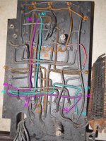
... can you post or email to Nate, copies of those nail-polish colourized wire photos I made of the backside of my '42 MG DC panel ...
Here you go:
EE17120 DC control panel - rear_c1.jpg
I'm not sure what the wiring diagram for this panel is, but it's not 2442, 2452, 2674 or 2679. It's in between 2452 and 2674. It's typical of early piggyback exciter machines. (If anyone has a copy of the wiring diagram for this panel, I would really like to have a scan.)

The pink wire running down the left (hinge) side of the panel to the group of 4 terminals is A2. The green wire that starts just above it and runs down the right side of the panel to the opposite group of 4 terminals is A1. The A1 and A2 terminals on the AP relay connect to the coil and to the spindle motor's armature. The pink wire that connects to the three terminals at the top is E1. The short, L-shaped green wire that connects to the fourth AP terminal is C5.

Here's an older version of the panel that I started tracing:
EE9456 DC Controller Back anno.jpg
This one corresponds to Wiring Diagrams 2442 and 2452 and appears to differ from the version shown in the first photo only in the presence (on this version) of a discharge resistor connected across the generator field. It's typical of the DC panel for machines with an inline exciter.

I've traced out and marked some of the wires and terminals on this one. A1 is in cyan; A2 is magenta; E1 (the positive lead from the exciter) is in orange; and C5, which provides power to one side of the forward and reverse contactor coil, is in dark brown. Connecting E1 to C5 makes that side of the F & R coils hot all the time, so that they are controlled only by the headstock drum switch. So you're looking for something odd with the brown C5 wire.

Cal
 
Relays in this form were common in the 50s, before solid state operational amplifiers and the like. They were used with photocells, directly operated with no amplifiers and in plate circuits of tubes. I would not be surprised to find that Struthers- Dunn did not make the relay, but rebranded Potter Brumfields, or some other. They were made with various coil resistances. Remember that you can generate a certain amount of magnetic flux in a given volume regardless of the voltage available by adjusting the wire size to draw the rated current for that size. Many turns of fine wire or a few of heavy comes out the same except for stacking factor issues. I once converted a 24 VDC solinoid to 6 V for a mobile ham rig dynamotor by unwinding the coil strung out in my driveway, folding it, and rewinding the multiple strands by hand. One strand six wire sizes larger would have been better, but I was a teenager with no money. Agonizing over the resistance is unnecessary. Find any of these relays and adjust the resistor accordingly. The relay I have (needing rewinding) has a 10 volt coil. The series resistor is 24,000 ohms, implying that the coil is 1000 ohms. The only problem would be that a very low resistance coil would mean more heat generated in the resistor.

Bill
 
Relays in this form were common in the 50s, before solid state operational amplifiers and the like. They were used with photocells, directly operated with no amplifiers and in plate circuits of tubes. I would not be surprised to find that Struthers- Dunn did not make the relay, but rebranded Potter Brumfields, or some other. They were made with various coil resistances. Remember that you can generate a certain amount of magnetic flux in a given volume regardless of the voltage available by adjusting the wire size to draw the rated current for that size. Many turns of fine wire or a few of heavy comes out the same except for stacking factor issues. ... The relay I have (needing rewinding) has a 10 volt coil. The series resistor is 24,000 ohms, implying that the coil is 1000 ohms. The only problem would be that a very low resistance coil would mean more heat generated in the resistor.

Bill
When you think about what this relay does, it's pretty amazing. It has to pick up at a 250 RPM (about 35% of full speed). IIRC, armature voltage for an unload DC motor is more or less proportional to speed, so at 35% of full speed, the relay is seeing about 80 Volts (35% of 230V). Yet it has to survive continuous operation at 230 Volts. That must be tricky to do.

Here's couple of Struthers-Dunn relays on eBay that are mechanically similar and might be a source of parts: The second one might work as is (with the correct series resistor), since it has a 10VDC coil.

Cal


After several hours of winding with the 10ee set up as the winder with the spool of wire held horizontally, I read Hit and Miss's reply and set the coil on end. this allowed me to up the speed of the winding to about 300rpm. for a while the inertia of the wire unwinding off the spool cause the wire to tie itself in knots (of sorts) as it rose to the bobbin I wound the coil on (original rectangular phenolic bobbin)

After seeing this happen (many times) I decided the wire winding off the spool needed a soft stop to keep it from winding off more than needed. I rolled up a piece of paper into a tube and taped this straw sized tube to the side of the spool, keeping the tape only at the bottom flange of the spool. the wire could then only unwind once before the soft stop stopped it from tangleing itself up. the tube was only taped at the bottom so the wire could pull past the tube as it was pulled past the top flange of the spool.

I tensioned the wire with a shop towel held between my index and thumb. Wind time was approximately 15 minutes.

The 10EE worked great as a winder and I had the feed set to .003" per rev. I just eyeballed each reverse location and pushed or pulled the feed reversal knob as needed.

Because the original paper layers were not used, I had to cap the coil so the wire would not slough off the sides. (learned this the hard way) I just cut pieces of cardboard for these caps.

I am amazed this worked. The wire is really difficult to work with a a dia of .003" breaks if you look at it wrong...

My final Ohms on the coil was 8500. Measured with a RadioShack analog meter.

Additionally, the DB resistors are running again (as a result of having a functional AP relay) Yay!!

The AP kick in point is about 300 RPM, the point at which it disengages (if not reversing) is about 50rpm. Seems its harder (if harder = voltage) to actuate than it is to de-actuate (if we call "actuated" the position that it switches to when the motors voltage is above a certain point) Not sure if I am conveying what I mean in this paragraph...

Thanks to EVERYONE who assisted with this problem!
 
Almost forgot. The wire guide was a sewing needle held in the clamping portion (where the indicator goes) on a Noga flexible indicator holder with magnetic base. The magnetic base was held down to the carrage, and thus travelled back and fourth with the .003" feed/rev.

I watched the needle eye for any signs of stripping the insulation off the wire but it never happened. I used a needle that was about 2.125" long and that has about a .020" wide eye of the needle.


Back
Top