What's new
What's new

Besides collet closing, can anyone think of reasons for a brake on Schaubliin 135 ?

Milacron

Administrator
Staff member
Joined
Dec 15, 2000
Location
SC, USA
I ask as a month or two back I removed the Warner electromagnetic brake from my 135 spindle motor .and was amazed at the difference without it. Night and day difference.. I never realized how smooth and quiet the 135 could be....every noise I always assumed was normal gear or variator noise was actually coming from that brake armature rattling as it rotated. In reality there is NO gear noise and NO variatior noise...just the swish of air from variator and spindle rotation !

Still, as I don't have the lever type collet change attachment but rather the conventional screw tube type, even in back gear, one can rotate the spindle a bit when tightening a collet very tight. So I figured maybe I should explore a better brake. Over months I gradually collected via eBay at cheap prices the critical three NOS parts needed for the "heavy duty" version of the Warner brake, where the armature moves on a spline rather than on three small shafts.

On Monday I finally got around to crawling in the lathe and installing the new spline style of armature. The results were a definite improvement over
the original....but now the issue was not so much increased noise as it was vibration, which I could feel touching the headstock and hand levers, where they was none when it was brakeless.

I thought about trying to remove the brake and perhaps better balancing it but then find out they are supposedly dynamically balanced at the factory anyway (although I see no evidence of added weights or drill holes anywhere on it) so I figure even if I improved it balance wise there would still be no way the lathe would be as perfect as it is with no brake.

Anyhow, as I can see a way to create a spindle lock to solve the collet issue, and the lathe comes to a stop just fine without a brake, just wondering if I am missing any scenarios where an electromagnetic brake would be desirable ? With it, the spindle would stop from 3000 RPM instantly.....but so what ? It stops without a brake from 3000 RPM in 2 or 3 seconds.....I can live with that. (that's with a collet in there however and suspect with a 3 jaw chuck it would rotate a bit longer...need to check that)

So, am I missing anything ?

I like a brake on a lathe. You are correct, it will take a lot longer to spin down with a chuck. I would look into balancing the new brake parts. How do they connect to the motor? Misalignment in a rotating mechanical connection will cause vibration for sure. Post some photos so we can see what you are up against.
 
I like a brake on a lathe. You are correct, it will take a lot longer to spin down with a chuck. I would look into balancing the new brake parts. How do they connect to the motor? Misalignment in a rotating mechanical connection will cause vibration for sure. Post some photos so we can see what you are up against.

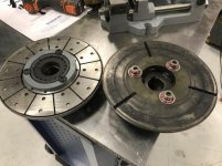
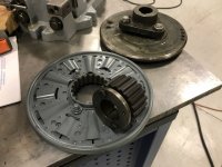
The original Warner armature assembly is on the right side in photos below and the new "heavy duty" version on the left side. The three items...armature, spline and 32mm motor arbor adapter (tapered to fit the slight ID taper of the spline), I bought gradually over time from three different eBay sellers at less than $180 total including shipping. This would have cost nearly $1000 from an industrial supply house.

The 32mm fit is perfect on the shaft and of course tightens up on there as two bolts pull it toward the spline....so there is zero play between motor arbor hub and spline and the accuracy and orientation seems excellent. It is a little surprising however to see no evidence of any balancing on the armature....no drill holes or added weights....but maybe they are made so "perfectly" they come out balanced regardless ??


IMG_1424.jpg IMG_1425.jpg IMG_1426.JPG
 
The original Warner armature assembly is on the right side in photos below and the new "heavy duty" version on the left side. The three items...armature, spline and 32mm motor arbor adapter (tapered to fit the slight ID taper of the spline), I bought gradually over time from three different eBay sellers at less than $180 total including shipping. This would have cost nearly $1000 from an industrial supply house.

The 32mm fit is perfect on the shaft and of course tightens up on there as two bolts pull it toward the spline....so there is zero play between motor arbor hub and spline and the accuracy and orientation seems excellent. It is a little surprising however to see no evidence of any balancing on the armature....no drill holes or added weights....but maybe they are made so "perfectly" they come out balanced regardless ??


View attachment 200644 View attachment 200645 View attachment 200646

As long as there is no run out on the rotating parts it has to be a balancing issue. The next step would to be to send all the rotating parts out to a proper industrial balancing co. I use Minneapolis Electronic Balancing Co. 612 781 2755 or there is probably some place closer to you.
 
As long as there is no run out on the rotating parts it has to be a balancing issue. The next step would to be to send all the rotating parts out to a proper industrial balancing co. I use Minneapolis Electronic Balancing Co. 612 781 2755 or there is probably some place closer to you.

1. Any vague notion of the cost ?

2. Would I need to supply a 32mm shaft as well ? (actually, the hub might tighten down nicely on a 1.25" shaft as 32mm is only .011" larger".....

Come to think of it, I think I have some 1.25 "ground and polished" steel rod in inventory.....I should try it and chuck it in the lathe spindle to see how much vibration there is that way.
 
1. Any vague notion of the cost ?

We had a stub shaft and centrifugal clutch slightly heavier that what you are showing spin-balanced locally for a few hundred $$. I would guess you'd have to send the assembly out of East Dogpatch, but maybe there's a local outfit that serves performance auto customers.
 
1. Any vague notion of the cost ?

2. Would I need to supply a 32mm shaft as well ? (actually, the hub might tighten down nicely on a 1.25" shaft as 32mm is only .011" larger".....

Come to think of it, I think I have some 1.25 "ground and polished" steel rod in inventory.....I should try it and chuck it in the lathe spindle to see how much vibration there is that way.

The last thing I had done was an armature, about 20" long, 75 lbs or so about 2 years ago, around 250.00 or so. you will need to provide a shaft with centers in each end.
 
The last thing I had done was an armature, about 20" long, 75 lbs or so about 2 years ago, around 250.00 or so. you will need to provide a shaft with centers in each end.
Are they particular about the center size and accuracy ? In other words, assuming minimal runout near the spindle, would drilling the ends on the Schaublin with no. 5 or 6 center drill be good enough....or they want a purpose built center grinder used ?

Suspect you're going to tell me the most accurate balancing will result from the most accurate center placement....

Anyhow, by locking it up on a 1.25 shaft and spinning the assembly in the lathe spindle that should confirm whether it actually needs balancing or not, which would go a long way toward inspiration to spend more on balancing than I spent on the whole works.......which is supposed to be balanced as part of the final manufacturing process.

But I suppose there is always the question of degree....to what degree was it balanced ?... and how is that expressed ? Is there such a thing as "perfectly" balanced.... or just like dimensions, there is no such thing as "perfect", only tolerances.

I made an arbor to hold Triumph Trident motorcycle clutches. I just drilled the centers. They balanced the arbor first then the clutches afterward.
 
Sorry, I don't understand this. If the centers are off-center, you can balance the shaft, but it will still not turn around its proper axis, and the brake disc will neither.

Charles

The holes were on center. Do you know what a '69-'75 Triumph Trident motorcycle clutch looks like? Doubt it. No point trying to describe the arbor then. Much more than a simple shaft. It ran true, but I wanted it balanced before use.
 
The holes were on center. Do you know what a '69-'75 Triumph Trident motorcycle clutch looks like? Doubt it. No point trying to describe the arbor then. Much more than a simple shaft. It ran true, but I wanted it balanced before use.
No need to doubt my knowledge of the motorcycle clutch, as I know nothing of motorcycles. But I was also referring to Milacron's original question:
Milacron said:
Are they particular about the center size and accuracy ? In other words, assuming minimal runout near the spindle, would drilling the ends on the Schaublin with no. 5 or 6 center drill be good enough....or they want a purpose built center grinder used ?
If a purpose made balancing shaft for the brake discs is not perfect including perfect centers, the balancing will not result in perfect balanced discs (not for his Schaublin 135).

Charles
 
the basic premise of out of balance is the centroid of the mass does not rotate on the axis of rotation.

So ideally you should have no runout firstly, the other bit is harder as its thin in will be just in one plane. Dynamically spinning it up will magnify the out of balance weight. You can initially do a static balance on knife edges or custom bearing see blocks if you like it is only a rough balance.

Check to see what machine they have, as to how they mount it and drive it.

Make up a mandrel to suit their machines dimensions and mounting, limit of fit on any adaptors is important to and will save you a few dollars.

Most likely they will not spin it on centres as i have never done it this way, but check in case they require it.
 
Maybe the vibration measurement app on a phone, seem to be several for the iPhone, would be sufficient for a quick and dirty assessment as to it there is a balance problem with the brake components. Three measurements with the lathe running would get you started. Bare machine, machine with arbor mounted and with brake components on arbor. Ought to be able to see any differences without complicated processing on a half decent app.

If you wanted a more sophisticated job some cermet microphones strapped to appropriate places and an analysis program, the audio hobby folks probably have something cheap and good enough, on the computer should work well.

Way back in around 1980 we did similar to remove serious output signal vibration contamination when testing low cost pyro-electric detector IR homing heads in a flying lab. Pyro-electric IR detectors respond DC to daylight and are rather better at the mechanical vibration detection thing than they are at there real job! Worked a treat. Very simple signal processing an combination techniques dug completely invisible signals out of the noise. Maybe a man week to design, build and sort then. All hardware. Gotta be much easier these days.

Clive


Back
Top