Korstolokki
Plastic
- Joined
- May 13, 2017
So, I got me a new lathe. VDF v630 that has been sitting still for the past 10 years so the first thing before I could start running it was to clean it good and get all the rust out. I decided to do the paint while I'm at because there were a lot of chips and scratches. However the only manual that I have is the one that is posted somewhere here in the forum and that is only an operating manual whit no info on the parts or how the thing should be serviced etc.
During that said cleaning process I have run into couple of mechanical conundrums to whose I would gladly accept some assistance.
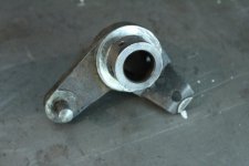
The first one is with the feed speed selection gear box: I was removing the knobs in order to put a fresh paint on the thing and when I pulled the locking lever that sits behind the main selector wheel of the link that it operates fell into the gearbox. So now in order to get it re connected I see no other way that to open the gear box. And this concerns me as I don't have any pictures of what is in there.

So my question is... Does anybody have any manual or picture of this type of gearbox? Or has someone any memories of taking something like this apart? It looks like the box is two assemblies with the selectors assembled on the front cover and gears to the back half... The thing is... ...is there how big of change of losing timing between the gears and selectors or dropping bunch of parts and not being able to definately tell where they dropped from if one would just unbolt the front and pull the two halves apart.
All help will be greatly appreciated, even educated guesses.
During that said cleaning process I have run into couple of mechanical conundrums to whose I would gladly accept some assistance.
The first one is with the feed speed selection gear box: I was removing the knobs in order to put a fresh paint on the thing and when I pulled the locking lever that sits behind the main selector wheel of the link that it operates fell into the gearbox. So now in order to get it re connected I see no other way that to open the gear box. And this concerns me as I don't have any pictures of what is in there.

So my question is... Does anybody have any manual or picture of this type of gearbox? Or has someone any memories of taking something like this apart? It looks like the box is two assemblies with the selectors assembled on the front cover and gears to the back half... The thing is... ...is there how big of change of losing timing between the gears and selectors or dropping bunch of parts and not being able to definately tell where they dropped from if one would just unbolt the front and pull the two halves apart.
All help will be greatly appreciated, even educated guesses.


