What's new
What's new

Tool (and offset) management

Motorsports-X

Hot Rolled
Joined
Nov 22, 2014
Location
Texas
I am in the process of teaching my guys how to use the tool offsets in such a manner that they only have to touch off one instance (vs touching every tool every time.) (A dial pin in one machine, and a haimer in the other) how do you guys control the offset for each tool and ensure that the tool gets changed propery and set with the correct offset? I thought of possibly laser marking the tool number on each tool, or possibly even the offset amount. Problem with offset amount is that you might change your system one day. So that pretty much leaves me with a "log" system. Check in/check out if you will. But without one dedicated tool room guy, it seems like that could, at some point, be a recipe for disaster. The other option i thought of was putting a tool height guage in the machine (like the $100 one, from edge technology) but that just ads another step to the process and my guys are already confused enough as it is ... though they are catching on to the methodolgy. Any tips?
 
Personally, if a tool comes out of the machine, it needs to be touched off again. If it's in the machine, the offset is fine.

I use one work offset for setting tools. On the Haas, it's G110. On the Yasnac, its J5 G54. The offset never changes. We use it only to set tools.
 
I, personally, am not a big fan of trying to eliminate tool touch-offs. I have seen it done with one of the methods mentioned and I've also seen an example where a reference point was established and measurements were recorded, then simply input at the next set-up. I believe if you will take the time to train a few guys, team leaders, the investment will pay off. To me it's all about building confidence in what you're doing. By training the the most efficient way to complete a certain operation, in this case tool touch-off, you will in turn create a workforce that feels good about what they have accomplished and moral will benefit. This is just the way I see it, I'm sure there are plenty who would beg to differ.
 
Personally, if a tool comes out of the machine, it needs to be touched off again. If it's in the machine, the offset is fine.

I use one work offset for setting tools. On the Haas, it's G110. On the Yasnac, its J5 G54. The offset never changes. We use it only to set tools.

Why do you need a work coordinate when touching tools Wes? Is this simply so you always set your tool-length offsets at the same point inside your work envelope?


How big is your shop Motorsports-X? It sounds to me like you are making a simple job complicated. Do your guys not build their own tooling?

Let me guess, the tools come out of the crib with a tag attached that has the offset written on it? I couldn't work there.

If your guys are already confused, then you need to keep this as simple as possible, or you are going to be dealing with tools burried in tables, vises, and parts.

Let me ask you this. How do you touch the tools off after they are put in the spindle?
 
I guess it really depends on the size of your outfit. Are you presenting tools, or just touching off as they setup new jobs?

If you aren't going to preset the tools, then Easley's method works well, and it's what I would do. If the tool leaves the machine, you "clear" that tool's offset, and touch-it off when it goes back in the machine. (Just changing inserts? Then probably not, but you get the idea...)

I've posted many times about a method for touching-off inside the machine if you want to search for it.

If you're trying to preset tools, what are you using? A fancy, optical CNC presetter, or something so simple as a height gage over-top of a tool vise? I've used both methods, and both work really well, so long as you USE THE SAME METHOD EVERY TIME...

What's important here, is that you
1- Pick a method,
2- Write it down, on clear, concise instructions, laminate them, and leave them by the machine/setup station.
3- Train, train, train your guys to do it the same way, every time...
 
Why do you need a work coordinate when touching tools Wes? Is this simply so you always set your tool-length offsets at the same point inside your work envelope?

For me it's a little easier. I use the 3D taster to set my work offsets. I used the 3D taster to set the offset that I use to set the tools. So, all the tools are set relative to the length of the 3D taster. This way, I can set the Z work offset using the taster and avoid having to do any math.

I've been doing it this way for years. It might not be the best method, but it works for me and it will work on any machine that has stored work offsets.

I used to use this method on my Tree 325 knee mill. The difference was that I had to set the offset with the taster first before setting the tools because it had a manual knee that would change the Z offset any time it was moved.
 
Why do you need a work coordinate when touching tools Wes? Is this simply so you always set your tool-length offsets at the same point inside your work envelope?


How big is your shop Motorsports-X? It sounds to me like you are making a simple job complicated. Do your guys not build their own tooling?

Let me guess, the tools come out of the crib with a tag attached that has the offset written on it? I couldn't work there.

If your guys are already confused, then you need to keep this as simple as possible, or you are going to be dealing with tools burried in tables, vises, and parts.

Let me ask you this. How do you touch the tools off after they are put in the spindle?
Not a big shop. But we do a huge variety of different work and can change as many as 5 or 6 tools per job. and can get a hot job and have to change over in the middle of a 20 hour surfacing run.

Im trying to accomplish 2 things. One, eliminate the setup time from touching tools. I know its minimal, but we dont have a touch probe so every minute counts, plus i beleive that touching off is not as accurate as cutting and measuring. Second, I want the CAM guys to have the libray built which save them a ton of time in locating the correct tool and getting the offset for it. (Basically thats the next area i need to standardize)

As far as the method, the reference tool it touched to any random surface in the machine. The machine position is recorded and that particular tool's offset is 0. On the following tools you simply touch the same point and record the difference in machine position and that amount is the tool offset. For a longer tool the number is postive and for a shorter tool the number is negative. We still use negative offsets no matter what the number is. (G43) i dont use positive offsets ever.

we always program that the top of the finished part is Z0. So when you get your job in the machine, you touch the reference tool (dial pin or taster) and part zero set the z and all the other tools follow. One touch instead of 3 or 5 or more.

The method isnt very complicated once you do it a while, its just new to my guys. Where i have problems is trying to control which holder/tool used which offset, and making sure if the tool is changed in the holder it gets set offline CORRECTLY. Correctly being the key. Right now im just using a go/no go shelf since i dont have a presetter yet. So if a tool is changed it goes on the no go shelf and the guys know if they use that tool they have to touch it and set the tool offset. Once that job is done they can take it out and put it on the go shelf (assuming the tool is still good) I just wonder if there is any "better way. " once the machinist get sorted on the process i need the cam department to follow the same process so i dont have to change it mid stream and cause more confusion. Obviously i need a presetter, but the context of my post is more about which tools are good to go and which are not.
 
For me it's a little easier. I use the 3D taster to set my work offsets. I used the 3D taster to set the offset that I use to set the tools. So, all the tools are set relative to the length of the 3D taster. This way, I can set the Z work offset using the taster and avoid having to do any math.

I've been doing it this way for years. It might not be the best method, but it works for me and it will work on any machine that has stored work offsets.

I used to use this method on my Tree 325 knee mill. The difference was that I had to set the offset with the taster first before setting the tools because it had a manual knee that would change the Z offset any time it was moved.
That the same thing i do. I personally feel that this is one of the best ways. A huge benefit is being able to program offsets from a master list into any machine and essentially "know" that its right. I want to get the touching out of the cncs. My beleif is that the cnc should be making chips, not measuring tools
 
For me it's a little easier. I use the 3D taster to set my work offsets. I used the 3D taster to set the offset that I use to set the tools. So, all the tools are set relative to the length of the 3D taster. This way, I can set the Z work offset using the taster and avoid having to do any math.

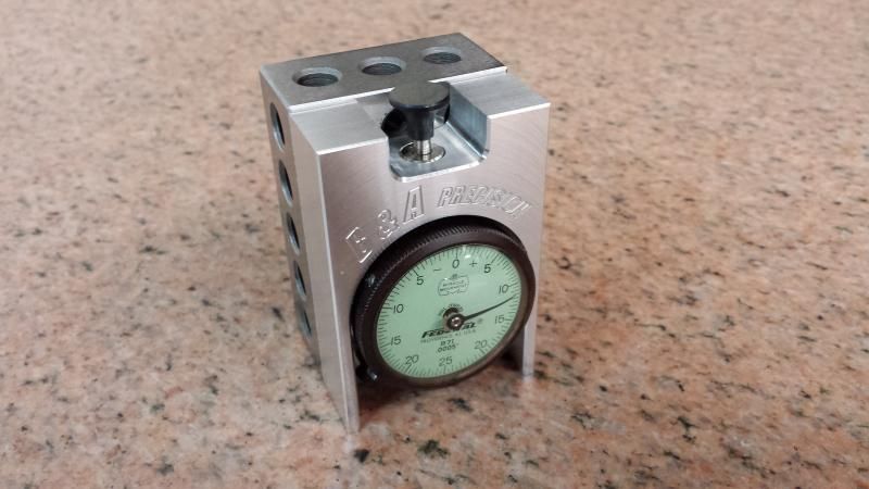
I guess that is kinda why I built my tool pre-setter to bolt to a 1-2-3 block:


Everything is relative to the top of the 1-2-3 block. Both tool-lengths and work-coordinates.

G54 Z0 = the distance from the top of the block to the part coordinate. So, I zero my taster on the block (origin Z on the operator position page), then run over and zero the taster wherever I want my Z0. Whatever the position page says (the difference from the top of the block, to Z0) goes in G54 Z. Works like a charm. And very simple. You almost can't screw it up. This is exactly how the Reneshaw system HAAS installs works as well.

As for touching tools? Just run that needle on the indicator to "0". It corresponds with the top of the block. It doesn't get much simpler.
 
I understand your point of view completly. But in order to be competative and get the work process as streamlined as possible, you have to use all tools avalible. CAM verification may come out perfect in the computer, but what happens when your machinist installs the tool 1" shorter than the cam programmer had planned? Maybe the holder hits a feature, maybe it doesnt. My guys are way to highly compenstated to stand there and watch a multi hour program run, when they can be doing other jobs that keep the business moving forward. If everyone is one the same page, and the cam programmer prints the tool list, then at a glance the machinist can see that everything is correct and all he has to do is load the tools, set the work offsets, press go, and walk away. Every shop is different and i feel that this is what is best for mine. There is 100 different ways to do things, and i wont tell anyone that their way is wrong.

That said, back to the original question. What system are you folks using to set and control the tools in the crib?is the go/no go shelf 'good enough'?
 
G54 Z0 = the distance from the top of the block to the part coordinate. So, I zero my taster on the block (origin Z on the operator position page), then run over and zero the taster wherever I want my Z0. Whatever the position page says (the difference from the top of the block, to Z0) goes in G54 Z. Works like a charm. And very simple. You almost can't screw it up. This is exactly how the Reneshaw system HAAS installs works as well.

As for touching tools? Just run that needle on the indicator to "0". It corresponds with the top of the block. It doesn't get much simpler.

I think it's simpler to not have to monkey with the operator Z origin. We use a 2" tall tool setter with an indicator. I set up the G110 offset to correspond to the taster being "0" at the "0" of the tool setter.

So, on my machine, all anyone has to do is MDI "G110". Then they touch the tools to the top of the tool setter. Then load the 3D taster and "0" it on the top of the part. Hit "Part Zero Set" on the desired work coordinate and away you go.

IMO, it can't get any simpler than that. I'm not gonna use the G110 for anything anyway.
 
I think all the methods described are essentially the same thing. Setting the tool length from a fixed non changing reference point, instead of from the work of each job. My method has one less step than yours as I dont have to do the g110. Just run the taster down to the z, part zero set, minus the extra stock for roughing and done. Again... 100 different ways
 
We have a small surface plate, dummy spindle, and height guage at every cell. I dont spend much time setting offsets because every tool has a number and they dont change. Every machine has a list on it of its' tools with radius and minimum set length. Offsets stored in machine. Part is programmed to the machines tooling.
 
I think what you are trying to accomplish is going to be a disaster. Lots of big shops try this and fail with full time tool crib guys. If you are concerned with tool setting time and don't want to worry about tool lengths, spend $2500 and get a Blum tool setter. Machine can set all the tools in a few minutes and automatically set the lengths into the offset page.

If they get set on a height stand, an optical presetter, or on the machine... won't change the fact that the tool is too short out of the holder. That is all about documentation from your programmer and machinists.

Maybe look into a tool setter that can download the offsets-into the machine? Or RFID chip in the pull studi is getting cheaper....

All this just to save 2 minutes a job change over...


All the verticals in the shop use a Edge style setter similar to the one Wheelie pictured. Its exactly 4.0" The other machines were purchased with Renishaw tool setters.
 
Also your method of setting tool lengths sounds scary as well...

Either use all negative lengths down to the work piece or use positive tool lengths. I think mixing them is going to cause you more grief.

Set all the tools off the same spot on the table and then measure up to the part for your G54 Z offset.

In my own experience I've found it easier for the guys setting the jobs up to always set the tools off the bottom surface on second/third operations instead of the top.
 
I've actually used the some +, some - TLO method before. It works out fine, hut here's the keys to making it work...

1- Pick as master tool (Make it a 3D taster...)
2- Setup a Tool-Vise on a surface plate, and use a height gage
3- Master the height gage over the "Zero'd" taster.
4- Put the Taster in the machine, and touch off your work offset.
5- Every other tool gets loaded onto the tool-vise, and "measured" with the height gage, and the measurement written down. It really doesn't matter what that measurement is. Sometimes it's going to be positive, sometimes negative.
6- Load the tools in the machine, and direct-input the numbers into the offset page.
7- Press Go, and watch your Distance-To-Go

It's actually a pretty good and repeatable method. The downside, is that if you ever change the length of the taster/master tool, all the other offsets are null, and you have to go back and re-teach each one. And what about the "Master" tool? Are you going to only have one, so that all the tools reference the same "master", (impractical) or go with a "master" tool for each machine, (it better be the same TYPE of tool for each - remember - we're standardizing...) and "null" each tool's measurements as they get pulled from the machine? I'd go the second route - taster for each machine - actually, taster/height gage/surface plate for each machine, and honestly, I like the NO-GO shelf idea. (Basically, if it's in a tool rack, it's a NO-GO tool....) I'd forget the GO shelf though - those tools should be sitting on the workbench/setup table, with the prints for the next job, and any other fixture/tooling needed for the next job.

I'll say this though. If you're running long-running cycles, AND you're also programming the next job, and gathering the tooling/seutp stuff needed, as this one is running, then it makes sense to go ahead and touch-off the TLO's outside the machine, as you're already gathering up tooling/setups/programs for the next job.

Not my prefered method, but it works.
 
Also your method of setting tool lengths sounds scary as well...

Either use all negative lengths down to the work piece or use positive tool lengths. I think mixing them is going to cause you more grief.

Set all the tools off the same spot on the table and then measure up to the part for your G54 Z offset.

In my own experience I've found it easier for the guys setting the jobs up to always set the tools off the bottom surface on second/third operations instead of the top.
You have to you positive and negative because your reference is the reference tool, not the guage line or the table. The gauge line reference is a popular method, but you have to use positve offset, which i refuse to do. I guess you could put the taster in a really long holder so that practically all your tools are shorter, but i dont see the point. Ill make a video of how we do it, its not complicated at all.


The mention of changing the Master is very valid. I hadnt thought of that, but it would stand to reason that your master tool length should be verified just like the rest of them. In order to make the same tool offset list valid on each machine, your masters would need to match. I can do that.
 
I understand your point of view completly. But in order to be competative and get the work process as streamlined as possible, you have to use all tools avalible. 1)CAM verification may come out perfect in the computer, but what happens when your machinist installs the tool 1" shorter than the cam programmer had planned? Maybe the holder hits a feature, maybe it doesnt. My guys are way to highly compenstated to stand there and watch a multi hour program run, when they can be doing other jobs that keep the business moving forward. 2) If everyone is one the same page, and the cam programmer prints the tool list, then at a glance the machinist can see that everything is correct and all he has to do is load the tools, set the work offsets, press go, and walk away. 3) Every shop is different and i feel that this is what is best for mine. There is 100 different ways to do things, and i wont tell anyone that their way is wrong.

That said, back to the original question. What system are you folks using to set and control the tools in the crib?is the go/no go shelf 'good enough'?

1) That is what set-up sheets are for.
2) You just answered #1 yourself.
3) Every shop, and every lead man, is different.

I agree with dstryr. It seems you have a couple different ways you could go.
The thing that makes me lean the way I do is that you stated that your guys are already confused.
Are they confused because they don't understand how tool offsets work? (I doubt it since you said they are compensated well).
Or, are they confused because nobody knows what the hell the other is doing? (I am assuming this is the case).
How big is this shop? How many CNCs? How many machinists?

Maybe a better question would be, how big does a shop need to be to warrant paying a guy to man the tool-crib?

I see what you are trying to do. And, you have good intentions. I just don't see you getting the results you are looking for, from the places you are looking to get them.

What do you do when you have 3 guys on big set-ups, all with lots of special tools, lets say 60 tools to build across the 3 jobs. And, you only have one guy in the crib? Then you have 3 guys standing around waiting on their cart full of tools. It sounds like a blame-game disaster in the making to me.

If it were up to me I would get after the CAM guys to put ALL the needed details on the set-up sheets. And let the guys build their own tools.
The only benefit I personally see from having a dedicated tool-crib attendant, is accountability of tooling, and an organized crib.

I don't know man. Its a tough call without being there.


Back
Top