Hi everyone,
This past September I came across a South Bend 13 down in the Milwaukee, WI area that was what I was looking for. As it always seems to go there's some backstory here - feel free to hop ahead a few paragraphs for the meat of this post. I've been slowly accumulating metalworking machines over the past 8 years. I had been looking for a South Bend (really a heavy 10) for several years, but had poor luck finding anything reasonably priced in my area. When this "deal" showed up I grabbed a moving truck and headed down to do a quick inspection. The machine was un-powered in a warehouse, but I wiggled things around and nothing stuck out too badly at the time.
The lathe is a 5ft bed version - I had anticipated it being shorter based upon the sellers description. This becomes important as when loading the lathe it no longer fit "east-west" but had to be placed "north-south" in the truck. As these things go, my original plan to rig the lathe from the truck didn't work due to it's new orientation and as the deadline for return of the rental truck loomed we pushed ahead knowing we were at the limits of our equipment (reach, weight, etc). I'll spare all the details but I learned what the 'south-end' of my South Bend looked like that day. The good news here is everyone stayed out of harms way, the lathe was cushioned by ripping the carriage door off my shop and no damage was done to the machine.
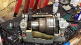
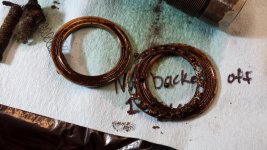
I've since been cleaning, lubing and repairing where necessary as I re-assemble the lathe. This isn't a tear-down resto like the awesome work bradjacob shows in his "South Bend 13 Restoration". Instead my goal is to make the machine functional and operational, but fix things that require attention.
![20150911_183019[1].jpg](https://www.practicalmachinist.com/forum/data/attachments/136/136299-fc3bc282a2be3e0c2f6556b0bd2ee509.jpg "20150911_183019[1].jpg")
![20150911_183022[1].jpg](https://www.practicalmachinist.com/forum/data/attachments/136/136300-9bd2cce416130f1f0dc6b90e008108ee.jpg "20150911_183022[1].jpg")
![20150911_183033[1].jpg](https://www.practicalmachinist.com/forum/data/attachments/136/136301-4e4bb3c15af260013fb729b615ac95c5.jpg "20150911_183033[1].jpg")
It will take a me a few days to get all the pics uploaded and catch you up to where I'm currently at. Hopefully I'll get enough time over the next week to upload everything.
Have a great week - Panz
This past September I came across a South Bend 13 down in the Milwaukee, WI area that was what I was looking for. As it always seems to go there's some backstory here - feel free to hop ahead a few paragraphs for the meat of this post. I've been slowly accumulating metalworking machines over the past 8 years. I had been looking for a South Bend (really a heavy 10) for several years, but had poor luck finding anything reasonably priced in my area. When this "deal" showed up I grabbed a moving truck and headed down to do a quick inspection. The machine was un-powered in a warehouse, but I wiggled things around and nothing stuck out too badly at the time.
The lathe is a 5ft bed version - I had anticipated it being shorter based upon the sellers description. This becomes important as when loading the lathe it no longer fit "east-west" but had to be placed "north-south" in the truck. As these things go, my original plan to rig the lathe from the truck didn't work due to it's new orientation and as the deadline for return of the rental truck loomed we pushed ahead knowing we were at the limits of our equipment (reach, weight, etc). I'll spare all the details but I learned what the 'south-end' of my South Bend looked like that day. The good news here is everyone stayed out of harms way, the lathe was cushioned by ripping the carriage door off my shop and no damage was done to the machine.
I've since been cleaning, lubing and repairing where necessary as I re-assemble the lathe. This isn't a tear-down resto like the awesome work bradjacob shows in his "South Bend 13 Restoration". Instead my goal is to make the machine functional and operational, but fix things that require attention.
It will take a me a few days to get all the pics uploaded and catch you up to where I'm currently at. Hopefully I'll get enough time over the next week to upload everything.
Have a great week - Panz