What's new
What's new

carriage stop question

Joined
Jan 25, 2005
Location
New Egypt, NJ
While working on my last project, which involved turning a shaft with a shoulder, I found the need for a carriage stop, which I do not possess. As a makshift device, which I'm afraid to tell y'all about... I can hear gasps from here!... I used a pair of vice grips (with pennies to protect the ways) clamped to the ways. This gave me a visual reference of when to stop the feed, but I still ended up unintentionally machining the shoulder a bit (only a few thousandths, but the goal was "zero" change to the shoulder). I guess with a real carriage stop, one adjusts it to the sesired location, then stops the power feed and runs the carriage in by hand the remaining distance? I'm headed to ebay right now to search for a carriage stop. Or maybe I could make one? I do have a milling machine I don't know how to use... sounds like a good way to make some scrap...
 
Or you could use a long stem dial indicator with a clamp block on the ways. Just don't run into your clamp with the feed going left or you could break some gears and parts. Just tilt your head on the mill to a 45 and make a groove for the way from a chunk of steel, i cut mine in my lathe with a milling setup...Bob
 
This sounds like a good newbie project! Could someone please post a photo and notes, so I could give it a try?
Also, is nec's idea correct? Stop the power feed short, and run into the shoulder by hand?
 
Woodman,

Metal Lathe Accessories sells a casting kit for a lathe carriage stop. I built one for my 10K to use with a 0-1" indicator, but you can also just use a solid stop.

MLA08.jpg


Here's one for sale on eBay that you could copy. Looks like it was homemade:

stop.jpg


Also, is nec's idea correct? Stop the power feed short, and run into the shoulder by hand?
Most definitely.

Paula
 
Thank you for the responses. I think I could copy that home-made job... I was about to say "easily", but that is how I always get into involved projects over my head! Have to go scavenging at the New Egypt Flea Market for big chunk of steel... looks like 1-1/4" ought to be enough... Thanks for the diagram, Paula.
 
In most cases the carriage stop with
indicator on it will not stop the carriage
dead if you feed into it. It will slide
along the ways. I try to not make a habit
of this but it does happen on rare occasions.

It's a bit tough to see but there's a one inch
travel indicator clamped to the ways under
my hand in this photo:

http://www.metalworking.com/RCM-gallery/files/Rozen,Jim/Jim.jpg

I would say this is possibly the single most
helpful accessory to that machine.

Jim
 
It's an old BMW RS54 rennsport race bike. That
was a photocopied page from that Guggenheim
book.

Wish I had one of those!

Jim
 
northeast confederate- wawoodman

You have a mill. You have a vise. Hopefully you have a set of parallels. You have some sort of stop to reposition the tool in the vise.

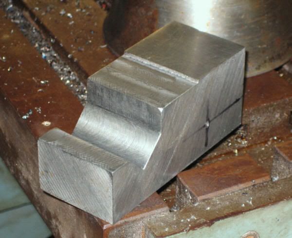
Get your hunk of 1-1/4" stock, and the first thing you'll want to do is square it up.

After that-
On top of your mill, you'll find a couple of bolts that will move the entire head forward and back. Bring the head forward, after dropping the table down.
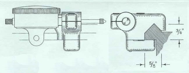
Also, you'll find some bolts that will loosen the head of your mill to allow the head to tilt forward- moving the tool towards the back of the machine. Move the head until you have it set at a 45 degree angle.
You may need to bring the head out some more now, as when you tilted the head things got a bunch closer, didn't they? Move the head until the tool is centered (or so) over the vise.
Clamp all the mill bolts tight, now, O.K.?

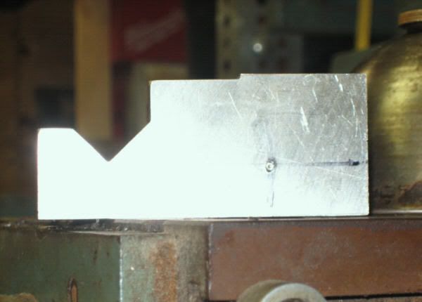
Clamp up your piece, against the work stop, and take a few passes until you can measure approximately .625 on the flats you've milled.
This will be towards one side of the stock-
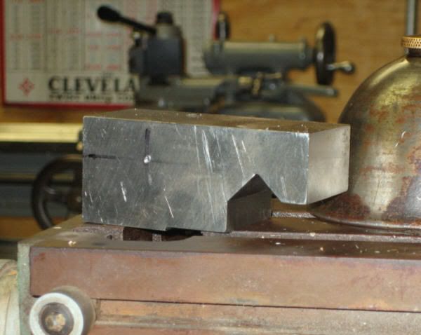
Allow room for 2 1/4"-20 holes and 1 5/16"-18 hole, all in a line parallel to your "V", to be explained later. Also, leave enough for the through hole for your stop bolt or indicator.
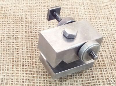
The 1/4"-20 holes don't show on Paula's pictures, but they are there and you'll want them.

Take the piece out, put it on the "V" of the way and see how it fits. You'll be pretty close. If not, back in the vise against your stop, and have at it until you like it.

For the clamp, machine a flat piece with a small relief, see Paula's pictures, and drill and tap your 1/4-20 and 5/16" holes. The 1/4" holes are for brass-tipped setscrews used for leveling and spacing the lower clamping plate, and transfer the 5/16" hole through to the top piece with the "V" way cut into it. Drill this transfer hole a letter"P' drill, to allow the 5/16" bolt clearance. This clamps the thing together.
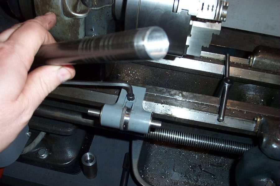
Next step is figuring out if you want to put an indicator in there or a stop bolt. That's up to you.

You can do this. With the price of junk micrometer stops on e-bay now over $80.00, this is a fun way to educate tourself on your mill and save some bucks at the same time.
When you get your job done, you'll need to tram the head of your mill so it's cutting straight, but that's a thought for a different thread- or PM me. I'll work you through it.
Again, you can.

Paula- I'm in awe of your resources, and also your ability to cut-and-paste things from your archives to this site. Great help. I've been a browser for some time, and your experience has helped innumerable people.

Billy :cool:
 
I had hoped that my next post was going to be a declaration of successful milling machine experimentation, with possibly a photo of the finished carriage stop. Unfortunately, the previous owner of this milling machine has installed a misfit motor, with a "found-it-in-the-pile" pulley, which is a single-sheave set-up and makes the spindle speed too fast for successful milling. I very quickly made my 4-flute 5/8" end mill so dull (I guess from excessive heat) that it beats the woekpiece instead of cutting it. Being a slow learner, I then exploded my 2-flute 5/8" end mill (before I figured out just what the problem was). So, back to the ol' South Bend to make a pulley, the correct sizes for which I ciphered using Machinery's Handbook. Billy, thatnks for your detailed instructions; after I get the mill running right, I'll get in touch with you. This being a specifically South Bend Lathe forum, I don't want to incense anyone by hijacking the forum for milling machine help. I'll report back with anything interesting.
 
Another design:

Two aluminum bars, about a 5/8 by 1/2 inch
in cross section.

The longer one has a 3/8 inch hole drilled in
it crosswised, to accept the shank of the dial
gage. A setscrew holds it in there.

Other end of the long one is put at a 45 degree
angle in the milling machine vise, and a
cut taken. This forms the V-way clamp.

The shorter aluminum bar is the clamp that
holds the upper one to the bed, it bears on the
underside of the ways. A screw tightens them
together. The lower clamp will try to rotate
when it is tightened though.

To fix that, a cut is made reducing the height of
the lower clamp except for a short portion at
the very front. So it now has a square boss
sticking up from the surface, by about a 0.1
inch or so.

The upper part then has a shallow slot milled
crosswised on the bottom, to accept the boss.

The boss in the slot acts like a key and prevents
things from getting all twisted up. I made
a cute clamping screw with a tall head, and a
tiny tommy bar to tighten the thing anywhere on
the bed without a wrench.

Jim
 
Hello again, everyone.
I'm back in buisiness with the mill... while glaring at it, I realized I could reposition the pulley on the motor shaft, and use the next "step" on the 'idler' pulley (I'm sure I'm not using the right terms, but you get the idea), which made the drive ratio from motor to idler 1:1, allowing me to slow the thing WAY down. Much happier now, doesn't eat end mills anymore. I'm trying to roughly copy the design Paula illustrated, and have so far taken a 1-1/2" square x 3" steel bar and machined the 5/8" v-groove, then test fitted it to the ways: 5/8" seems a bit too wide, as the horizontal plane at the 'rear' of the v-groove does not contact the corresponding surface of the ways. Seems like that doesn't matter, though, as long as the 'v' fits the ways, which it does. Once a bolt cinches the ways between the v-grooved block and the flat one which will go beneath, it should stay put, right? One other thought: Is it sensible to make some sort of 'convertible' stop, which could accept either a dial indicator or a screw stop?
 
Is it sensible to make some sort of 'convertible' stop, which could accept either a dial indicator or a screw stop?
Certainly. Just ream the hole to 3/8" to fit an indicator stem, and then make a 3/8" dia. solid rod to use when you want a fixed stop.

Your pictures didn't come through, for some reason. Note that you need to have a separate set of IMG tags surrounding each picture. Even so, the links seem to be incomplete. If you want to, you can email them to me and I will be happy to post them here.

Paula
 
Sorry, I cannot seem to get the pictures in the post. They're on the computer, but I can't figure out how to tranfer them even after reading the instructions, and experimenting...
 
Thanks, Paula! Since then I've drilled the center-punched hole to 21/64, and am now trying to decide how to get to 3/8" accurately. I do not have a reamer, as you suggested, Paula. I also drilled the hole for the "pinch" bolt through the top. Have to knock off for the day, probably won't get back in the basement for a few days (job REALLY interferes with the rest of my life!), I'll keep y'all "posted". My 14-yr old daughter thinks she can figure out the photos, next time I'll try her idea!


Back
Top