What's new
What's new

9" Large Dial Conversion

Halligan

Aluminum
Joined
Oct 6, 2011
Location
Massachusetts
So I'm in the process of doing a large dial conversion and I have everything pretty much set, but I have one question. Do the oil holes in the bushing align with the oil port in the cross slide or are they offset from it? On my small dials it ends up sitting somewhere around 60 degrees and there are two holes, one directly across from another. Should there be only one? If you were to have two and have it aligned with the oil hole wouldn't the oil just run out the threads on the bottom?
 
for the best lubrication the hole should be offset - the groove cut in the bushing(where the oil hole is) combines with the threaded hole(3/4"x 16 tpi) in the cross slide casting to create a reservoir.
it`s not critical where the hole is, since the oil doesn`t have anywhere else to go, it has to go in the hole.

as long as it`s not directly in line with the oil hole in the cross slide it will be fine- if it were directly in line the oil would just sit in the reservoir and not feed into the hole, defeating the purpose of the reservoir.

only one hole is necessary.

ps- a 2" dial combined with a 1/2" longer-than-stock bushing seems to be ideal for 9" and 10k`s - i have that and a 1.750" dial on my compound - there is no interference when swinging the compound around and the extra 1/2" for the bushing keeps you from pinching your fingers...:)
 
Awesome thanks for the info. Now I was able to get it all together. It turns smooth as silk and best of all I can actually read it :D
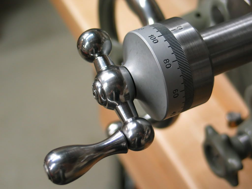
. THe dials were purchased from SBLatheman (Thanks Ted ;)) I had roughed out a dial but couldn't really find a way to accurately index it and cut it on the lathe that I thought worked. I have no mill.........yet. So for about the same price as some sort of jig and number punch set I was able to get two 1.750 200 Div stock dials. So picture time! Unfortunately I lost the pictures of cutting the busshing out of the 2" stock I used. All metal is 12L14.


THe real dial next to my rough blank. Pretty close
IMG-20121124-00015.jpg


The old feedscrew shaft was cut off, then the gear part trimmed by the length of the roller thrust bearing, drilled and reamed to .4995. Then a 1/2" diameter piece cut longer then I needed was pressfit and held with permanant loctite. I used 1/2" so I had something to machine down to the 3/8" size I needed so it remained perfectly concentric with the gear of the screw.
After all machining:
IMG-20121123-00003.jpg


Threading the 12/24 thread for the nut. I used the boring bar holder to align the die.
IMG-20121123-00004.jpg


I cut a groove in the shaft with a threading tool turned sideways. This will hold any gunk that builds up and also hold some oil inside the bushing
IMG-20121124-00016.jpg


All the parts laid out after cutting the oil hole in the bushing and the spanner wrench hole.
IMG-20121124-00013.jpg


The finished product next to the original
IMG-20121124-00022.jpg


IMG-20121124-00019.jpg
 
I used 271. It was all I could find at local auto stores and I didn't want to wait till monday to go to Grainger. It's for bolts but I made a test piece and let it dry over night. Held one end in a vise and tried to spin it out with a pair of channellocks. They spun on the rod and I couldn't budge it so I was happy with that. Applied a little heat and did the same thing and it popped right out so at least I know I can take it apart if something catastrophic happens.
 
Your dials are not complete. You need to paint the dial with some black (slow drying paint) - then wipe it off. It will remain in the witness marks and will visually "pop out" aginast the pickled finish.

Here's what they'll look like when done:
IMG_4456-1.jpg


Here's me doing it to my 13" dials:
ae454b3b75e09735af6b624fa616c31b.jpg
 
Do you know where to buy the thrust bearings? Or, do these have a special name?

Thanks,

the ball thrust bearings were purchased from MSC and made by Boston Gear. O.D. 11/16- I.D. 3/8- thickness 9/32 These are the ONLY ones that will fit.

The needle bearings and washers were bought from MSC also O.D. .813- I.D. 3/8- thickness .078 and the two thinest washers to go with it at .032

Now onto the compound
 
Ok got around to making the compound screw. I taped the making of it incase anyone is interested.

https://www.youtube.com/watch?v=2BJ6_8Xk1IU Differences between large and small dial (200 graduation direct diameter reading and small 100 graduation radius reading),The Plan, and Grinding an Acme toolbit.

https://www.youtube.com/watch?v=DwgzCHfIXUo Machining the blank to correct diameters prior to threading.

https://www.youtube.com/watch?v=BAyUfPn2bck Cutting the ACME thread and setting change gears on a model B

https://www.youtube.com/watch?v=tm6H_9qp_0E Completing the screw assembly (bearing faces, collar register, ball-crank register, ballcrank retaining nut thread)

And now the pics :D

Wilmington-20121205-00032.jpg


The Parts:
Wilmington-20121205-00033.jpg


Acme thread: This was my first time cutting one and grinding the acme bit. Didn't come out too bad
Wilmington-20121205-00037.jpg
 
using the geared shaft?

I plan on doing this to my 11" R model cross slide, but somehow it seems different looking than the 9s or 10s?
Did you in fact use the original gear shaft, and made the outer shaft longer?
That is what I plan on doing , I think the shaft on the 11" is larger than 3/8" , I think?
Also is seems to me that the busing thread on the 11" is farther up in the slide than just next to the front edge, but will have to look closer tomorrow?
I replaced the acme thread today and it went differently than what is described for the 9 and 10s.
Mine had a bare shaft in front of the gear splines for about 1.125 so I cut the threads off in front of that and drilled and reamed it for .350 to just to where the splines start ,, then turned my acme down to that size, polished to press fit and filed the .005 flat on it and coated w/ 680 and inserted it while the acme was still in the chuck, ran the tail stock up behind it and took it on and off until I got all the air out and all the glue in. then tightened the tails stock up on it till tomorrow and will drill for a taper pin, I think I have a #1 and a reamer. my pin will be about .550+ infornt of the splines.
I am almost positive my front part of the shaft is very different, Will try for measurements and pictures tomorrow.
Ron
 
Yes I used the gear and acme thread. It's not worn very much. I trimmed the gear by the width of the bearing, adjusted my chuck to as close to 0 runout as I could, drilled and reamed for .4997, held a 1/2" pice of stock in my drill chuck and loctitedit in place. Then I machined the 1/2" down to the 3/8" diameter I needed. I did it like that to make sure the shaft remained perfectly concentric with the gear.
 
Finally finished the compound. Turns smooth as silk with the bearings and only has about .010-.015 backlash on the large dial which would make only about .005-.007 of actual crosslide movement. There is no interference between the ballcranks unless you have them on top of one another with the compound backed all the way out which will never happen. I have a couple videos up of the making of the bushing. The rest should be up by the end of the weekend.

https://www.youtube.com/watch?v=xuhfFg7cBP4

https://www.youtube.com/watch?v=sdddj-99DqI


Wilmington-20121214-00048.jpg


Wilmington-20121214-00047.jpg


Wilmington-20121214-00046.jpg


Wilmington-20121214-00044.jpg


Back
Top