What's new
What's new

GE tri-cad motor wiring help 8 wires

Greenemachin

Plastic
Joined
Nov 22, 2017
I have a vintage South Bend Vertical mill i have been trying everywere to find help and no one around here has any knowledge about this type of wiring,Been searching forums here and other places but seems like i have a ODDBALL Motor or something LOL.,
I have all the specs,Pictures and try to supply any information i can BUT,I know nothing about Motor wiring language,I am A Wrench head so i am not scared to try things and get hands dirty thou HEHE
Now to the basics::::
I am new hear so i will get this site figured out also cause i do know my PUTERS also
South Bend Vertical Mill
Tag Says::::
GE Tri-Clad motor (Model 5KC18oDJ208)
PH)1 HP)1 No. PW
Volts 115/230 Amps 13/6.5
Cycles 60 Rpm 1725 service factor 1.25
Time rating Cont. FRAME 180x Type KC
Code K Conn. Diag. 732A640

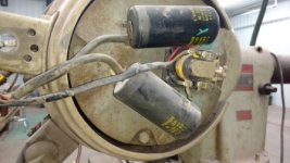
No wiring diagram on motor or under any plates this is all i can come up with. I will post pictures now,
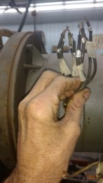
I want to let you know I have paired up the wires with tape as i checked them with OHMs meter. Wires are all marked with metal tab with only a# on them 2-8 and there is one wire not labeled which i assume is # 1
I want to wire this up as 220
line in will be 2 hots and a groundimg_20180128_095443103.jpgimg_20180125_194213640.jpgimg_20180128_095337163.jpgimg_20180125_194234967.jpgimg_20180125_194223903.jpg
Reply With Quote Reply With Quote
 

Attachments

  • IMG_20180128_095443103.jpg
    IMG_20180128_095443103.jpg
    43.7 KB · Views: 373
  • IMG_20180128_095337163.jpg
    IMG_20180128_095337163.jpg
    43.1 KB · Views: 317
  • IMG_20180125_194234967.jpg
    IMG_20180125_194234967.jpg
    53.6 KB · Views: 198
  • IMG_20180125_194223903.jpg
    IMG_20180125_194223903.jpg
    49 KB · Views: 372
  • IMG_20180125_194213640.jpg
    IMG_20180125_194213640.jpg
    52.9 KB · Views: 609
I'm not sure, but you might try this in the transformer and wiring section.

I guess there must be 4 windings, 2 for each "phase". In high voltage the pairs would be in series. In low voltage (your situation), the pairs would be in parallel. I have no idea how you can find which pairs belong together if the motor was not wired up at all when you got it.

It's single phase, so reversing it requires switching the polarity of the start winding relative to the run winding. That might be something we tackle once you figure out the winding pairs.

It looks like a guess and check method to me.

I did try it in other section but everyone reads but no help, i have been on here for 2 months and seems like a good site to find help. i can't find an answer anywhere.

But thank you for your RESPONSE
 
I tore in to it deeper today i can take more pictures now and show you the windings now if this helps
 
You're going to have to put voltage to the windings and find out which windings have to be paired together.

It's a single phase motor, so it has a run winding and a start winding. Since it has a centrifugal switch, the motor may shuts off the start winding once the motor is up to speed. or, it may just disconnect the start capacitor from the winding.

Are the resistance values of all the windings the same?
 
I have taken motor out of case to see direction of the pairs of wires ,Now i have marked 4 wires that go one direction with yellow tape and marked the wires returning from winding in Blue tape,Now i know i won't make mistake of putting power to same wire going both direction, This would probably fry something .
i checked resistance with Ohm;s meter ,about 6 wires read about same e(1.4) ohms 2 wire read about 1.8 or more,, so i assume these wires are my stert windintj wires Correct? Now what?
Jerry
 
I am fairly familiar with electric motors and their various configurations but I have to say your post has me stumped. Your resistance measurements suggest 3 pairs or 3 windings with the same resistance and one which is different. Usually for a dual voltage single phase motor there would be 4 pairs the same and one different with the "different" one being the start winding. Unless there is some internal connection we can't see, the configuration you have doesn't make any sense.

If you go here Single-Phase Induction Motors you can find a pretty complete discussion of the various configurations possible and the only 8 lead single phase motor has two start windings which you probably don't have.

I notice in your pictures that the leads have small silver tags on them. Are those by any chance metal crimp-on tags that might have ID's stamped on them? Something like "T-1"?

You might use your ohm-meter to check to see if there is continuity between any of the pairs you've pulled out. That would support the idea that there is an internal connection that you can't see and would help in figuring out how the coils need to be connected to make it run.
 
No internal connection, tags are numbered 2-8 one lead no number i assume it;s #1
also i thought i stated there is 4 pairs (8 wires) with one set different ohms Which i am thinking are start windings.
with that being said 5&8 revese wires 1&2 being start winding how do i hook up with 2 Capacitors and relay with my 4 wires coming in from Drum switch?
 
suggest 3 good pics.
1-the machine itself
2-the motor
3-the switch

No,one can help much without that to go on.

This is all I can offer-

http://www.wswells.com/data/howto/robert_lang/BULLETIN_645B.pdf

I have posted the pictures you are asking for, they are all in the start of my thread perfect photos here as far as i thought, this why i posted pics of the switch caps relay and motor in beginning cause i didn't wanna look totally stupid here asking for help


Back
Top