What's new
What's new

Heavy 10 Electrical Mounting Question

duckfarmer27

Stainless
Joined
Nov 4, 2005
Location
Upstate NY
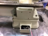
I'm in the process of putting my Heavy 10 back together. Shipped January 1945. Per the card the electrical components on it are original. It has a manual motor starter (with proper heaters installed) mounted on the back side of the bed - see pictures. When I tore this apart there was a fair amount of swarf and oil that had migrated into the opening in the Headstock End Leg, as SB called it, where the wiring from the motor terminates. I should note this lathe is mounted on a cabinet. There is a slightly variable gap between the casting and the bottom of the starter box, maximum opening probably 1/4 inch.

I'm not that familiar with these and am just curious as to why there seemed to be no sealing between the casting and the box. My solution is going to be RTV - unless there is some part missing.

Probably can chalk this one up to SB trivia as I realize there were several different options as to how these were wired. And apologies for the Iphone pictures which rotate between my computer and here.

Dale
 

Attachments

  • Back Starter 3.jpg
    Back Starter 3.jpg
    77.2 KB · Views: 172
  • Back Starter 2.jpg
    Back Starter 2.jpg
    75 KB · Views: 169
  • Back Starter 1.jpg
    Back Starter 1.jpg
    89.3 KB · Views: 172
Erich -

Thanks, realize that. Thread when I got the late is here http://www.practicalmachinist.com/vb/south-bend-lathes/my-new-70-year-old-heavy-10-a-292135/

I'm just slow getting to work on it!

Jim -

I'm going to disagree with you. Per the original thread, and the SB 'birth certificate' pictured below, this lathe was for mounting in an Army mobile machine shop - based on that is where it came out of and the angle iron welded onto the back of it. My memory says the date on the paper inside both the manual starter and drum switch are dated 1943 and 1944 (did not go out to the shop to check this rainy Easter Sunday morning). Drum switch is mounted on a cast iron base at the left end (facing lathe) of the headstock. When I tore it down all the wiring was period correct - fabric outer covering from motor in old flex conduit, etc. Rubber covered multi connector cable from starter to switch, with connections made in the starter box. Things are just totally period correct from my experience. There are no extra mounting holes anywhere on the machine. Now I'm open to you being correct but I sure don't think so.

In my looking on here - and other sites - I have not seen a lathe like this configuration. I'm sure there are others out there and was hoping someone would pipe up. Maybe Ted will see this and can shed some light on it.

This lathe was built in late 1944 and shipped early January 1945. Around the peak of WW2 production with everything going full blast. I could imagine some kind of seal being around the bottom of the box, but then I can also imagine an off shift or overtime causing something to be missed - did not spend most of my working life as a manufacturing engineer and not learn that one!

To me a mystery and I'm looking for anyone else with similar vintage as to how it was done. Like I said, easy enough to seal with RTV. Knockout in box is very good alignment with the flex conduit end in the lathe base.

On edit I see the card is hard to read. Here is what it is:
Drum Switch - 790 Less switch arm Wiring - 1447-PD
Linestarter -Manual non-rev. starter west class 10-100 so style ## 1040456
1638-5D-1045 bench ##SBLW 1638 special w/special angle iron clips welded to back of bench for wall fastening

It also has the GE 3/4 hp instant reversing motor, 115 volt.

Dale

While out in the lawn with the grandkids stopped in the shop long enough to grab data.

Starter is a Westinghouse De-Ion Motor Watchman Type DNW, 2 pole. Size 0, Class 10-100-SO, Style No. 1040456-E, Data sheet pasted in dated 4-43 while heater data sheet is dated 1-44
Drum Switch is a Cutler Hammer Size 0 Drum Controller No. 5441H27A, data sheet dated April, 1942

All which goes to prove my memory is not working 100%! But I still think both are original.
 

Attachments

  • Birth Certificate.jpg
    Birth Certificate.jpg
    93.7 KB · Views: 89
Last edited:
If there was a seal, it may have just been a heavy paper gasket that fell apart and was lost sometime in the last 75 years. That end leg is not the standard one, so it was obviously meant to have something installed there. The typical one doesn't have the opening like yours does.
 
If there was a seal, it may have just been a heavy paper gasket that fell apart and was lost sometime in the last 75 years. That end leg is not the standard one, so it was obviously meant to have something installed there. The typical one doesn't have the opening like yours does.

Gadget73 -

You are guessing about the same as me on there maybe being some kind of gasket there. I've never messed with a larger SB before, so don't know what an end leg is supposed to look like. This machine was a strange one when built I am thinking. Came with metric gearing but sold to government. Has a US stamp on the bed - not an anchor or 'flaming p**s pot' stamp. Installed in an Army truck, most likely 2 1/2 ton mobile machine shop. But the metric has me scratching my head a bit. I can't think - offhand - of any Army equipment used in WW2 that was metric.

The mystery will probably just continue. But you never know - throwing it out on this forum is probably the best place to fish for an answer.

Dale
 
My heavy 10 is not as unique as your lathe and bench. But it was made in 1943 and sold to the US Navy. It is also equipped to cut Metric threads. I think the Govmint was just checking every box on the order form after all "there is a war on!!!!"
 
Maybe the U.S. stuff wasn't metric BUT the allies fighting beside them certainly were...good to be able to get them up and running too.

Very cool machine...that's the kind I think is worth saving and restoring.
 
Maybe the U.S. stuff wasn't metric BUT the allies fighting beside them certainly were...good to be able to get them up and running too.

iwananew10k -

I'm not sure how much metric was involved on our side. Would be interesting to talk to someone who actually had knowledge in that area. I don't believe Brits at that point did much with metric. All the other minor players (Free French, Poles, Norwegians, etc) were using Brit/US equipment as those who made it to the West came with nothing other than the shirts on their backs. That leaves the Soviet Union. But again, there we supplied a lot of trucks, etc.

I'm retired Army and poked the Ordnance Museum about this, trying to figure out what a couple of missing pieces were in the customized drawers. They could not come up with anything. I'll have to dig out the guys email and ask him if they have knowledge of what, if any, equipment we used that required metric capability. This is an area I know just enough to be dangerous and ask questions.

Dale
 
Not to open a new can of worms, but are you sure you want the switch handle on the headstock of the machine.I like to make it so I can stop the machine without reaching past the chuck.A lot of old lathes had the switch or pushbutton station on the headstock.This became a legal problem for some manufacturers at one time or another.You could be injured by whatever made it necessary to stop the machine quickly.The availability of flexible metallic conduit and wire with oil resistant insulation makes it easy to put them where you choose.
 
Not to open a new can of worms, but are you sure you want the switch handle on the headstock of the machine.I like to make it so I can stop the machine without reaching past the chuck.A lot of old lathes had the switch or pushbutton station on the headstock.This became a legal problem for some manufacturers at one time or another.You could be injured by whatever made it necessary to stop the machine quickly.The availability of flexible metallic conduit and wire with oil resistant insulation makes it easy to put them where you choose.

k3vyl -

Well, I guess I could move it but had not even considered it. Of course you could also make the argument it should have EPO and guards on it - but I'm a retired engineering manager who had to worry about all that stuff when I was working - we were one of the first OSHA Star sites and I've been there and done that more than once. Also had 33 years of the Army (most of it reserve component) where safety was a huge part of my job. I well understand the human component in the chain of events that ends with a mishap. But I have also seen the safety crazies actually cause problems. Like Will Rodgers said - the trouble with common sense is that it is not so common.

If I do anything I'd probably put a contactor (wall mount) ahead of the starter and put a couple push button stations off the pan with mushroom off switches. With that manual contactor on the back of the headstock it is not convenient to start with. Have had my table saw rigged up that way for probably 25 years - left thigh is well trained to turn it off with swinging bar activated stop switch mounted on bottom of front fence. I really don't want to change this old machine much. It is in amazing shape for it's age and I'd like to let any changes be minor - usually I don't worry about that at all but I've grown to like this machine for some reason. I'll have to paw through the stock of electrical controls - you at least have me thinking. If it was just me, probably not. But as my grandson has an interest in everything in the shop I might just reconsider - although I am trying to teach him the way I was brought up with machinery, which I believe was the right way based on the results.

Dale
 
I was an electrician for DuPont for 40 years so you know where I got it.They put stops on top of stops,The part about the legal problems came from SBL themselves.One of their parts men told me they had to make switch/pushbutton location changes due to some mishaps years ago.I still have the tree mounted switch on my 13" UMD lathe,but I located the switches on my workshop lathe and my 13" Regal to the tail end.
The mushroom stop idea is particularly good for what you have in mind.A maintained mushroom button wired for enable-disable might suit. Those so called structural C clamps will allow you to mount what you need without drilling the CI or the pan.One of these days I will relocate the tree switch on that 13.
 
I was an electrician for DuPont for 40 years so you know where I got it.
k3vyl -

If I would have looked at your location I would have guessed that! My working life was IBM manufacturing plant, which was real close to how you guys operated. Then we got sold to Lockheed Martin, but the old culture pretty much carried on at least until I retired. Of course that is not bad - I have been in other plants where when I walked out said to myself that neither I nor any of my family would work in that place. Even my grandfather was picky on which coal mine he worked in - and as a hunkie he really did not have much of a choice but was smart enough to know the better ones.

Dale
 
There is still a lot of DuPont around here and the safety culture still exists. I hope it survives the Dow merger. I have been retired for a few years so I’m really not in touch.
Those C clamps I mentioned are a Gedney product from the electrical supply house. There are several sizes available. I have a set of T handle Allen wrenches mounted on the tailstock end of the pan of my 13” SBL with them. I have put socket head screws on everything that has to be manipulated regularly.They are particularly handy for the oil screws.
 
Last edited:
Another thought about that heavy 10 with metric capabilitys and an instant reversing motor.If it did not have a metric thread dial,it would have been necessary to be able to reverse it because you cant open the nuts without a dial.Those dials were expensive.Just another piece that might help the other pieces fit..


Back
Top