What's new
What's new

how anyone can make a gear in a pinch

iwananew10K

Diamond
Joined
Sep 12, 2010
Location
moscow,ohio
a recent project requires me to make a gear that I cannot get commercially.
I figure this happens to many guys and can stall an otherwise good project.
it`s actually not hard to make one- all you need is some 0-1 steel and you can make your own cutter.

first read this- (thanks to John Stevenson)

GEAR CUTTING

note that the chart shown is for 20PA gears, your South Bend uses 14.5PA - for the 14.5PA chart see post #25 from this HSM thread (thanks again to John Stevenson for working it up)

Gear cutting with forms - Page 3

with this knowledge it`s just a matter of plugging in values and making your cutter- I take a little different route to making it that any hack can duplicate... it`s a spur gear for a lathe and it doesn`t require super precision to make a gear that will work nicely in this type of application.

I`m just going to show how I make the cutter - indexing and cutting the gear is up to you...:)

continued in the next post
 
first we need a radius gage - in my case I need a .171" radius so I just turned a piece of scrap to .342" diameter.
using this "gage" and nothing more than a bench grinder, ground a 3/8" HSS blank to match the "gage"

 
then chuck up a piece of 3/4" 0-1, set your compound to 0 degrees(parallel with the spindle)

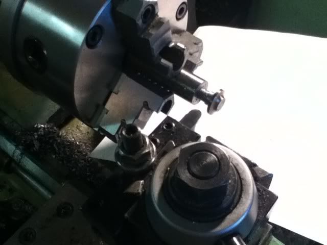
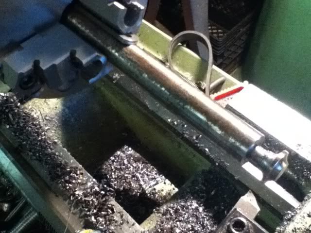
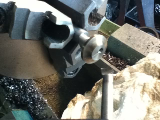
use the chart and cut the basic profile of your cutter- first one side,feeding with the cross slide to the required depth then advance the compound the specified distance and cut the other side.

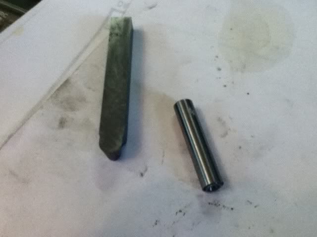
you will end up with something like this-( it helps to cut clearance first to make room for your form tool)

 
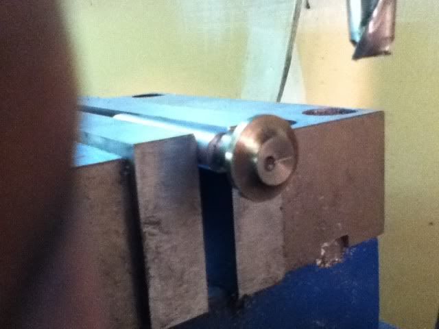
part it off at the length you want and rechuck it- rotate the spindle by hand and locate the "high spot"
use a boring bar set on center or some sharp tool to scribe a line across the end.

 
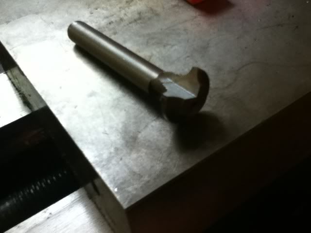
mill or grind down to the scribed line to expose what will be your cutting edge- take care to get the orientation correct or you may end up with a left hand cutter....:)

 
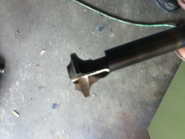
grind the cutting face to make a nice sharp edge - a small grinding wheel makes a nice cupped face to give it a positive rake for easy cutting.
I used a dremel tool.


that`s it!
you now have a cutter to make your gear. works in all materials I`ve tried so far- cast iron,steel,plastic, aluminum....

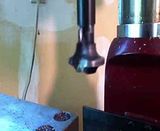
this video will show why it works- the eccentric gives it relief when it cuts.

have fun!!

 
not really an involute at all since it`s a constant radius, but plenty close enough.:)
if someone wanted to take the time you could certainly do better than commercially bought cutters since they are only approximations anyway with it being "correct" for only the lowest number of teeth of the range.
ie- a commercial #4 cutter for 26-34 teeth is really only correct for 26 teeth
 
Button gear cutters

Looking at the table for Button gear cutters for 14.5 PA gears referred to and linked below to Post # 25, I see a note that the numbers in the tables are probably metric. My thought also w as that the numbers were in metric format even if they said inches, but in doing a little math, I believe that the numbers would be too small to be metric.

For instance, the diameter of a button for a #4 cutter, DP 18 with 14.5 PA from the chart, if metric would be 8.22m / 18 = .4566m, less than 20 thou. Mighty small to be a cutter.

Wonder if anyone has actually checked to see if the tables are metric or inches

a recent project requires me to make a gear that I cannot get commercially.
I figure this happens to many guys and can stall an otherwise good project.
it`s actually not hard to make one- all you need is some 0-1 steel and you can make your own cutter.

first read this- (thanks to John Stevenson)

GEAR CUTTING

note that the chart shown is for 20PA gears, your South Bend uses 14.5PA - for the 14.5PA chart see post #25 from this HSM thread (thanks again to John Stevenson for working it up)

Gear cutting with forms - Page 3

with this knowledge it`s just a matter of plugging in values and making your cutter- I take a little different route to making it that any hack can duplicate... it`s a spur gear for a lathe and it doesn`t require super precision to make a gear that will work nicely in this type of application.

I`m just going to show how I make the cutter - indexing and cutting the gear is up to you...:)

continued in the next post
 
heat up the cutting end to bright glowing "cherry" and dunk it in old oil to cool it off.

There is no reason at all to use old oil. You have to use water or oil, depending on what steel you use.

Here is my method, if you have a CNC with rotary axis. The tool is as simple as can be.
Be patient, it starts with cutting a rack.

Edit: Ooops, wrong video.

Nick
 
I admit I`ve never crunched any of the numbers, but I can say that following the tables makes a good gear.
also, this is kind of a "method of last resort", if I can buy the needed gear, or even get the cutter(without going broke!), that would be my first choice.

no reason to use old oil???

the greenies are gonna get you, Nick!

(neat video!)
 
There is no reason at all to use old oil.
...
Here is my method, if you have a CNC with rotary axis.
I know I probably don't speak for myself when I say that some of us are stuck with old oil and no CNC with rotary axis...;)

I admit I`ve never crunched any of the numbers, but I can say that following the tables makes a good gear.
also, this is kind of a "method of last resort", if I can buy the needed gear, or even get the cutter(without going broke!), that would be my first choice.
Chad,

The one thing I don't understand is why it needs to be eccentric. Why does it need that relief, is that to get the concaveness to the profile of the gear? That part I didn't fully understand.

no reason to use old oil???

the greenies are gonna get you, Nick!
Thanks for the laugh...I needed that...;)

Cheers,
Alan
 
kind of hard to explain but as the cutter comes around to the "high"point and then starts to fall away side relief is "generated"

I wish I could remember where I saw it but someone had posted a great computer animation of the cutting action.

you could also make the cutter without the offset and stick it in a boring head and use that to get the offset- that works great for aluminum and plastics but I was using steel(4140 I think) and wanted it to be as stiff as possible.
 
kind of hard to explain but as the cutter comes around to the "high"point and then starts to fall away side relief is "generated"
When I was thinking about it in my head, I could see how it being elliptical would gouge into the piece, and you want the high side of the eccentricity to create that.

What I wasn't sure of, and still a bit unclear is that in how you kinda tried to describe it, it seems that it changes the rake of the tooth, in relation to the gear, if that is even the correct terminology...

In Nick's video at 4:05 it states:

"This is the generative part. The flanks of the teeth get convex by this process, albeit the *tool has straight sides.". (*Nick may have had a typo, English is probably not his first language?)

In Nick's video, then around 7:20 you can see how the helical gear is concave.

What I was thinking is that if you can visualize the eccentric cutter cutting the metal, the cutter would be digging deeper in the center than from either side, so it would be cutting a convex, I believe. You can see the convexity much clearer on the helical cutter done on the CNC. I *think* the CNC is able to compensate for the eccentricity by rotating the work about 15 degrees back and forth. In his case he was rotating the work about 15 degrees back and forth, He was essentially using his cutter on a boring head to get the offset, as you elude to in the last comment of your post.

OTOH, my head could be on upside down, it's getting late...;)

Do you have a pic of the 4140 gear that you made with your eccentric cutter? I'd like to see it if you do. Others might also.

This is good stuff to know. Thanks for that video Nick!

Cheers,
Alan
 
Nick is using a generating method with a straight flanked tool, much like a hob. Chad is using a form cutter with curved flanks, like the sets of 8 B&S style cutters. The one thing they both have in common (and so do most other cutting tools) is relief behind the cutting edge. Using an eccentric produces this automatically. Nick had to grind relief in his cutter.

allan


Back
Top