Imakechips
Cast Iron
- Joined
- Feb 18, 2005
- Location
- North texas
It took me a couple of hours(I was by myself), but with the help of my Honda Rancher and a Hilift jack I managed to get it off the trailer and into the shop. I will put some pics up of the lathe and how I decided to move it around when I figure out how(will search this site for info). Now I need to rewire the shop(will post pics of the ancient wiring), purchase and install a RPC(probably), and clean the machine up.
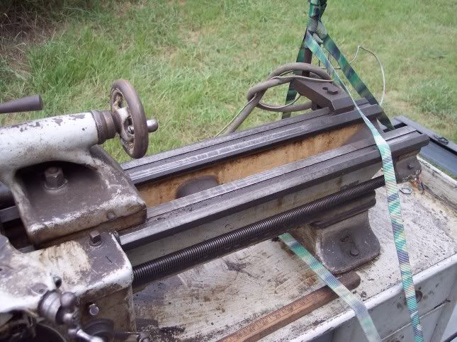
the ways
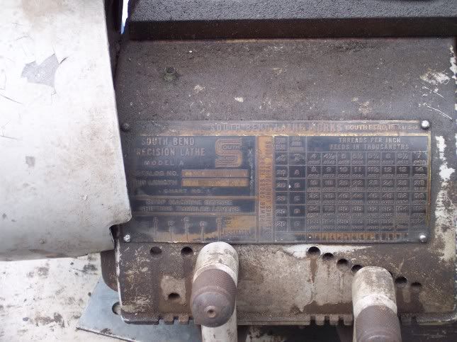
the gearbox
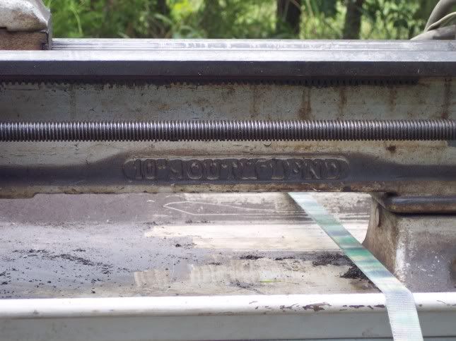
10" South Bend
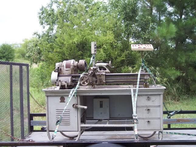
Lathe on trailer
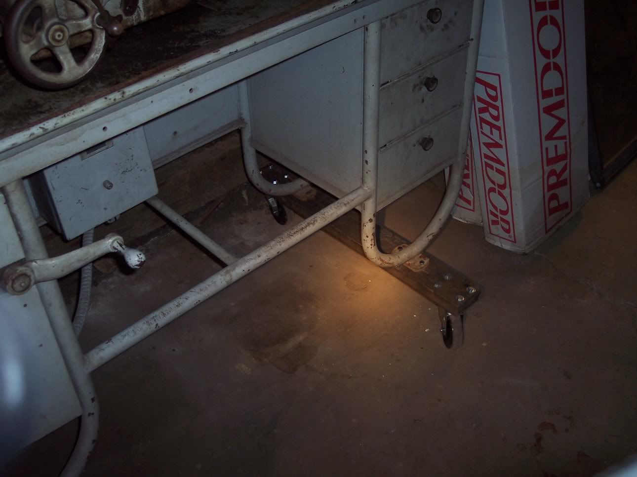
pic of 2x4 and casters
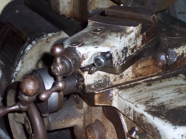
picture of someone's idea of gib adjustmnet
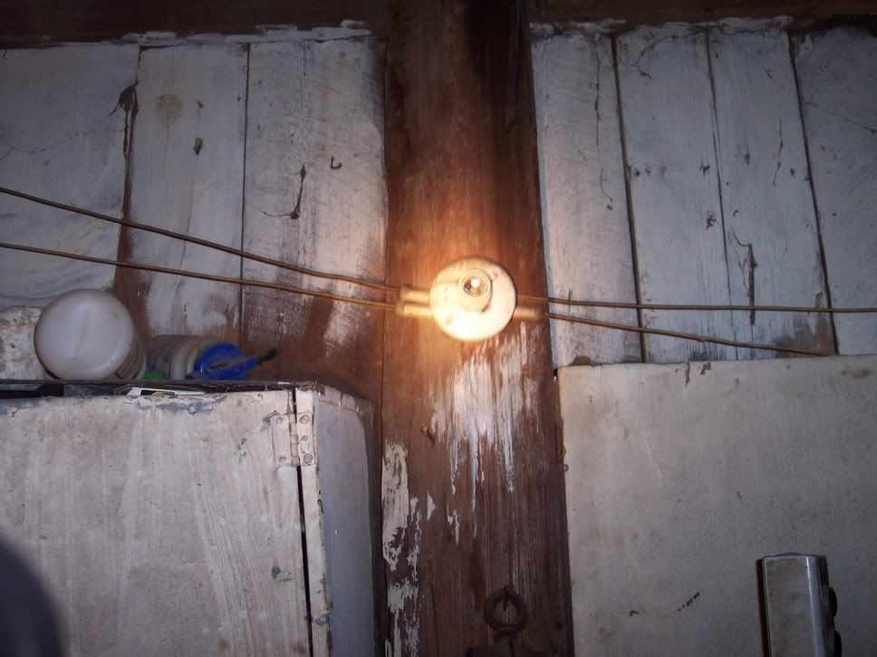
picture of the wiring and light
Well, at least I figured that out!
This topic is also posted in the general section at http://www.practicalmachinist.com/ubb/ultimatebb.php?ubb=get_topic;f=1;t=013727
[ 08-18-2005, 06:21 PM: Message edited by: Imakechips ]
the ways
the gearbox
10" South Bend
Lathe on trailer
pic of 2x4 and casters
picture of someone's idea of gib adjustmnet
picture of the wiring and light
Well, at least I figured that out!
This topic is also posted in the general section at http://www.practicalmachinist.com/ubb/ultimatebb.php?ubb=get_topic;f=1;t=013727
[ 08-18-2005, 06:21 PM: Message edited by: Imakechips ]
