What's new
What's new

Installing a DRO on a SB 10?

Pete F

Titanium
Joined
Jul 30, 2008
Location
Sydney, Australia
Sorry guys, I'm sure this comes up regularly, but "DRO" is too short to be caught by the search engine.

I wonder what options others have come up with in regard installing a scale on the cross slide of a SB 9/10 or similar sized lathe? There really isn't much room at all and I can see each option will involve compromises, however I'm very keen to see what others have come up with.

Thanks
 
I've never considered installing a DRO on a South Bend 10, either 10K or 10L. There's already too much conflict over real estate between the tailstock, carriage, carriage stop, taper attachment, and various sizes of chucks to even think about how the DRO hardware would fit. If you add in a quick change tool post, the real estate problem gets worse. It just seems to me the DRO hardware would be in the way all the time and be at risk of damage all of the time. That stuff belongs on a bigger lathe.
 
I have successfully installed a DRO on my 9A, 4.5" bed lathe. It was mounted to the back of my lathe, in place of the taper attachment. It also gave me a shelf to attach a worklight or a dial indicator stand. It worked out very well. And does not interfere with my follow rest or Mica undercutting attachment.

I started to write a tutorial on how I did it, but I got sidetracked. I will try to finish it and post It.

Stay safe and have fun.

Joe.
 
Thanks Joe, yes it seems like out the back is the place for it. I'm leaning toward a position that's out the back but also partly down the tailstock side. I will be keen to see some photographs of what you came up with.
 
Plenty of SB 9" and similar sized lathes have been fitted with standard glass scales, which is what I have to go on this machine. There's no doubt that it CAN be done, but it's just a question of different placement options and the compromises they involve.
 
Here's a 3-D CAD rendering of what I did, alongwith a couple of pictures of this product.

Drawing2a.jpgDscn0678.jpgImgp1319.jpg

Stay safe and have fun.

Joe.
 
Thanks Joe, I've seen some people mount the Z scale as you have. It saves drilling and tapping holes in the bed and is a good solution from that perspective. I think I will just bite the bullet and drill/spot face appropriate points on the bed casting, but I'll see.

I was curious however as to what you have over the top of that X slide? Is that just an aluminium way cover?
 
The cross slide I used was from metal lathe accessories, so it has a Flat and square section at the back that I could bolt an extension to. The extension was in 2 pieces, first an aluminum block to support an aluminum box approximately 10" long. I used a piece of box aluminum because it gave me the rigidity that I wanted, without the weight.

The only problem that I had with it was It barely touched the Mica undercutting attachment. Placing a washer between the attachment and the saddle eliminated this problem.

Other than that everything is clear. All gibb screws are accessible, and I have full range of motion on the saddle and cross slide.

Note: accurately machining and drilling the bed is harder than it looks. To properly do it, You need access to a milling machine that will support the entire length of the bed. I don't advise trying it without It. The mounting points need to be perfectly aligned and parallel to each other. Anything less can cause problems. Using this setup, I was able to get to 0.0000 parallel In 36". And it did not involve taking the lathe apart. Besides my little mill drill was not up to the task.

Stay safe and have fun.

Joe.
 
Joe I will make up a jig to index off the bottom of the way to drill and spot face the bed, that side of things shouldn't be an issue (famous last words).
 
Joe I will make up a jig to index off the bottom of the way to drill and spot face the bed, that side of things shouldn't be an issue (famous last words).

As an additional precaution, drill the holes oversize and be prepared to dowel pin after the piece is adjusted parallel. That is how the factory installed taper attachments.
 
I wanted to follow this up and hope it will help others.

Rather than pasting the whole shebang on here again, here's a link to how this all worked out for me. Hopefully it will be of assistance to others who may be planning an installation of a DRO on a SB 9/10" lathe. The Hercus is a 10" and it was quite a squeeze to get the X scale in. As I mentioned on that forum, I'm very happy with how it all worked out and can't think of anything I would have done differently if i had to do it all again. It was no doubt a little "over-built", but I'd rather put my name to too strong than not strong enough!

Hercus 260 DRO installation
 
Oh that's right, I forgot about that. Sorry! I'll repost the thing here if anyone is interested, I guess it doesn't make much sense without the pictures!
 
Ok here is a copy and paste of the appropriate threads from the other forum, complete with pictures.

I decided to fit the Z scale first as I think that's the easier of the two, at least the one with the most room. As much as I hate to drill holes in what was a brand new lathe, it needs to be done. I was initially going to mount the scales on 2 turned "pads", but I wasn't happy with that so changed my mind.

After deciding exactly where I was going to place it, I drilled using some 7 mm holes using a hardened V block as a drill guide. Because the casting is both rough and has draft I'm referencing the V block off the bottom of the lathe's ways to ensure the hole is perpendicular to the ways. Not essential in this case, but would have been with my initial idea of a mounting pad. I'd consider it good practice anyway rather than just jamming it in at any old angle. Another small V block protects the ways. The hole was then tapped M8 using a piece of aluminium as a tap guide since I couldn't fit the tap in the V block guide.

Drill Guide.jpg Tap Guide.jpg

I initially tried a "puck" type of arrangement and it worked just fine. I simply turned up some aluminium pucks and threaded them with an M8 spigot one end and tapped M6 the other end for the scales to mount to. the problem with this is it didn't really offer any adjustment, and I wasn't happy with it. Instead I decided to scrap that idea and make up some pads with jacking screws that can jack against the uneven casting and will allow the pad to pivot on the central M8 cap screw. I then have adjustment in all planes as I can move the pad in and out with the M8, but still provide a very rigid platform for the scales.

I use my Tapmatics a lot, and they're worth it even for small runs like this. Tapping all the holes took about 60 seconds, and it doesn't take much time to set up. This is the bigger 50X.

Z pad fabrication.jpg

Once installed the pad is aligned horizontally with the lathe's carriage, vertically with a precision cube sitting on the ways, and in depth with a depth dial indicator.

Z pads.jpg Aligning Z pad.jpg
 
I decided to put it in the rear keyway, so everything is machined as per Hercus' screw ups ie I would have used a smaller diameter bolt so it didn't break through the sides of the keyway, but that's how they did it on their other brackets, hence so is mine. I wanted to avoid any unnecessary holes in the machine but wanted it very rigid, hence the keyway. It needs to be either tapped on, or have the securing cap screw pull it on, as I made the keyway a light interference fit. Once fitted the machine should be able to be hung from it, it's super-rigid!!

Z bracket.jpg

I gave it a quick lick with powder coat. I didn't blow off the part after cleaning and some acetone remained in the crack between the two parts. I noticed it once I'd powder coated it but before baking, but wanted to leave it to see what would happen. I thought the powder would flow out but it didn't. No biggie and I'm often grateful to see mistakes so I know what to do on more important projects. This powder is called "Black Carbide", it's a light texture finish and I quite like it on projects. The camera makes it look much rougher than it does in reality.

Powder coated bracket.jpg

This gives a better idea of how the back of the machine looks. Admittedly it's a little over engineered, but I spend a lot of time chasing my own tail on the Aciera, where the problem wasn't what I thought it was, and was instead a very slight flexing of the DRO scale bracket. This sucker ain't gunna flex!!!

Rear of machine.jpg
 
Next thing to tackle is the X axis. Initially I'd planned to have it sticking fully out the back of the cross slide, however it wouldn't fit within the splash back. I settled on half out the back and down the side. I was about to start fitting it there when I decided to have one final go at getting it across the saddle, and thought I may be able to JUST get it in there without blocking too much if I replaced the square head compound locks with grub screws. The gib screws of the cross slide would be covered, but I didn't consider this a big deal, as they don't need to be adjusted often. The scale is mounted to a backing piece of aluminium, and by making a slot for the gib screws and milling away a fair amount for the top of the cross slide, I was able to get it in there with just a couple of washers as shims. I didn't take photos of that, but again used grub screws to jack the scale vertical. it makes everything very rigid.

I finished up pulling the saddle off as it was easier to work on that way. I tried to get the armour off and insert a right angle bend, but the fitting seemed to be glued in position. Instead I was able to get it in by outting right toward the front and the cable could just bend around the available radius. I spotted the mounting holes though to the casting so I could see where to position the read head bracket.

X layout.jpg

This is the bracket for the read head. Again using a central pivot and jacking screws to allow alignment. U shaped milled section to the left is what remained of an original slot in the material. It seemed to serve no purpose and I don't know why it was there, or even if it was supposed to be there.

X Bracket.jpg

Once everything was assembled it was obvious the gib bolts for the saddle were hitting the Z scale cover. That whole gib seemed a bit Mickey Mouse to me, so I decided to counter bore it just under the thickness of the spring washer to move the bolts up 2 millimetres. Something that should have been done in the factory really.

Saddle Gib before.jpg Saddle Gib couter bored.jpg

Almost finished!
 
Ok job is done and bottled up, though I've been away a lot lately so haven't had much opportunity to use it in anger.

As I suggested above, I replaced the square head bolts with grub screws on the compound, something I think is better anyway. I tend to leave my compound at around 28 degrees so I can thread without having to change anything, and at that setting the top slide makes getting to one of the locking bolts awkward. I can get an allen key in there much easier. I took a photo of the headstock side, as the other side is difficult to see.

Compound Lock.jpg

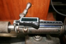
This is the tailstock view of the X axis scale. I finished up taking the cover off for the moment, as it needs to be removed to get even an allen key in to the compound locking grub screw. As I said all along, it's a VERY tight fit to get this all in there! It's only 2 screws and no big deal to whip the cover off (as mentioned, I tend to leave my compound on 28 degrees unless I'm cutting a taper etc, so it's not like I'm doing it every day), however the screw is also covered by the top slide at this angle What I'll most likely do is modify the cover to bring a bracket down to the front and put a knurled know in there and at the back to replace the 2 screws. I think the best way to tackle this will emerge with use. I don't like to require more tools to make adjustments to the lathe than I need to, so taking out the requirement for a screw driver is a good thing in itself. While I cleaned up the X bracket from the shots above when i was fabricating it, i didn't ever think it would be seen so didn't fuss over it. I think things look a lot neater with the cover in place, and it serves to protect the scale from the tailstock ramming in to it, so I'll certainly try to work out a way to get the cover back on where it doesn't become a PIA in use.

Completed Side.jpg

The back of the machine, sorry about the poor quality photo. Next time I'm at Jaycar or similar I'll pick up some black spiral cable wrap and wrap the cables. I have coolant, light, and the two DRO armoured cables so I just secured them together with cable ties for the moment. The wrap I have here is too thin to do all that I think, and I'll need some heavier duty wrap. The bundle then feeds up over the top of the splash back. I can traverse the length of the bed without anything getting tight or the cables dragging through the chip tray. They just hang down the back of the machine where they can't be seen and are out of harm's way. I like to keep crap out of my chip tray, as makes clearing the chips easier.

Completed Rear.jpg

I don't know if this photo means that much, but is a closer look at the back. Everything is in the same position as before and nothing is adversely affected in the lathe operation as far as I can tell. The loops in the DRO cable on the X scale is very deliberate as it's the minimum bending radius and it needs to be in that position so as not to snag the scale when the cross slide is would back in.

Completed Rear 2.jpg

Here's the completed machine, again another crappy photo. Maybe I had grease on the lens of something, I don't know. I have a cabinet drawer full of QCTP holders and I may build a rack for at least some of the more common ones I use all the time at the machine, and number the holders. The DRO can be programmed with tool offset, and that would be a handy feature. When I'm working I tend to keep my QCTP tools in the tray just to the left of the tailstock when I'm swapping them in and out, but it's not a very eloquent solution at the best of times. A rack would be much better and I have a design in mind using some left over aluminium extrusion I was using for T-slot in woodworking jigs, and that should tidy things up considerably.

Completed Lathe.jpg

All in all I'm pleased and haven't come across anything that is a major head slap moment where I discovered I can't [insert idiot moment here]. Obviously I can't get the tailstock quite as close to the carriage as I could previously, but whether that's going to be an issue remains to be seen. The functions on all these Chinese readouts seem to be very similar from what I've seen in reading through the manuals, and I've already found a couple of gotcha's if measuring taper when in diameter mode. The main advantage I think will be with the Z to be honest, as accurately measuring longer lengths was always a bit of a PIA previously. I haven't used the tool offset function yet, but that's also one I'm looking forward to using as I tend to use different inserts depending on whether I'm hogging off material compared to finishing.

The readout itself is bolted to the wall. I would have preferred it over the headstock, and it will reach across there, but obviously on this lathe design I need to open the cover very regularly. I didn't want the DRO in line with the chuck (the stain on the wall says all), quite apart from not reaching over the chuck. It seems ok where it is, but these are only small lathes, so I can put it pretty much anywhere along it I like.

That's about it. Other than the few things I mentioned above, I'm calling that one done and good to go.
 
I have a 1922 25-Y I added DRO's to existing holes, did not want to add new holes. I still have to add one more to add in the back.
 

Attachments

  • Tailstock DRO.jpg
    Tailstock DRO.jpg
    88.4 KB · Views: 494
  • Cross Feed DRO.jpg
    Cross Feed DRO.jpg
    90.6 KB · Views: 359


Back
Top