Paula
Titanium
- Joined
- Sep 16, 2005
- Location
- Indiana, USA
Hi all,
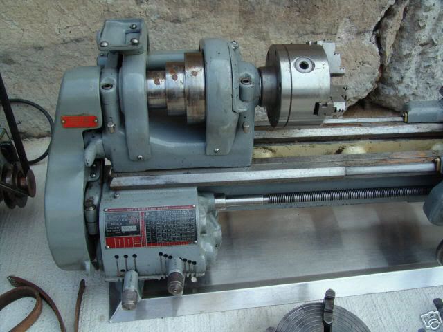
My 9A lathe restoration project is almost done, but one accessory I wanted to add before the lathe can be considered complete is a good 3-jaw chuck. My lathe came with a very nice Skinner 6” 4-jaw chuck, which will get a lot of use, but a decent 3-jaw can be used for a lot of the less-demanding jobs, or those which can be finished in a single setup.
My first mistake was to purchase a used chuck. I DO NOT RECOMMEND THIS. You will likely wind up with the target of many years’ worth of abuse by previous owners. (By the way, if anyone’s interested in a decent anchor for their fishing boat, with a nifty built-in rope gripper, contact me off-line.) So with that lesson learned, I decided to purchase a new Bison 5” (125mm) 3-jaw chuck, with an unmachined, threaded adapter plate. The Bison is a Polish-made chuck, of decent quality and a good value. Not the best, but certainly not the worst, and just fine for occasional home-shop use.
I decided against the “direct mount” type because I wanted the chuck to run as true as possible on my lathe. Given the inherent inaccuracies of a scroll-type chuck, I figured it could use every break it could get. So, I purchased the bare chuck along with a rough-machined adapter plate, pre-threaded 1-1/2"-8 to fit the spindle nose of my lathe. This means that the seating face and shoulder which locate the chuck will be machined on the actual lathe that the chuck is to be mounted. This way, any irregularities of my particular spindle nose will be compensated for.
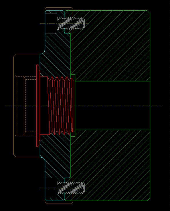
I tried not to include too many pictures, since I know how they can affect the loading time for those without high-speed connections. The first one is a cross-section that I did on the CAD system, to arrive at the desired mounting configuration. The lathe’s spindle nose is shown in red, a cross-section of the chuck body is shown in green, and the machined adapter plate is shown in blue. The original, unmachined outline of the of the adapter plate is shown in brown:
One of my goals was to reduce the overhang of the chuck to an absolute minimum. My theory is that every millimeter that the chuck sticks out past the end of the spindle bearing amplifies the effective bearing clearance, increasing the possibility of deflection and chatter at the workpiece. Therefore, you will notice that I tried to get the spindle nose to fit as close to the chuck as possible, even to the point of needing to counterbore the scroll retaining plate slightly to clear the tip of the spindle thread. One drawback to this configuration is that it slightly reduces the amount of workpiece clearance behind the jaws, but I figure the overhang issue trumps it. Another drawback is the amount of material that needs to be removed from the adapter plate’s hub! I toyed with the idea of setting this up on the saw somehow, but later decided that this is what automatic cross-feed is good for.
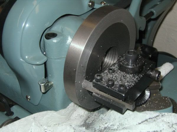
Since I was going to be modifying the hub, and this operation would affect the alignment of the plate to the spindle nose, it needed to be done before machining the registration surfaces for the chuck. The first step is to thread the adapter plate onto the spindle and take a skim cut on the face and O.D., to get these surfaces in alignment with the spindle thread:
NOTE: The swarf from machining cast iron is some nasty, gritty stuff. So I took steps, where practical, to catch the chips as they were produced. Also, after each phase of the machining process, I took the time to clean up and re-lubricate the lathe.
After machining the face and O.D. of the plate, I removed it from the spindle and mouned the 4-jaw chuck. The adapter plate was carefully centered in the 4-jaw so that the thread’s counterbore was in alignment with the lathe axis. Now I was ready to begin machining the hub:
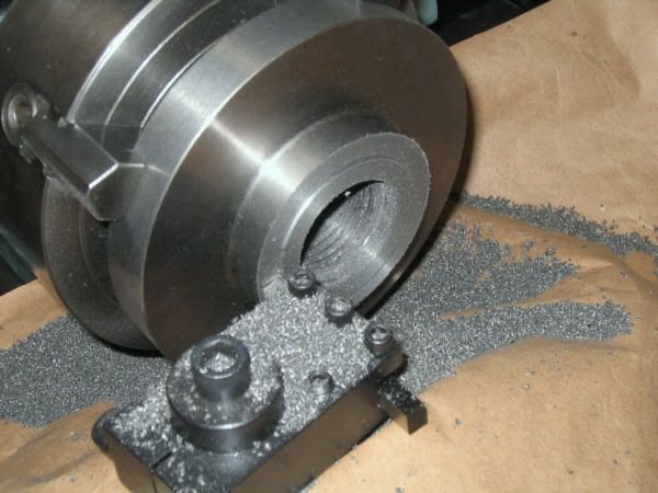
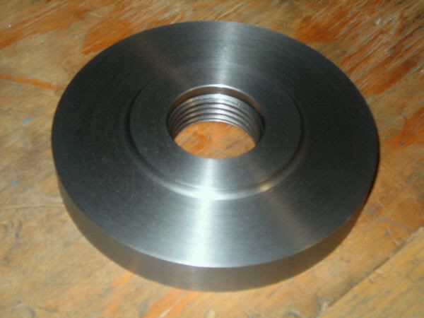
I had to make quite a few chips getting the hub down to size! But even so, it didn’t seem to take that long. After facing the hub to the correct length, I used a stubby boring bit to counterbore the threads to the required I.D. and depth, along with a 30 degree lead-in. Also, since there was visible runout of the rear face of the adapter plate, I decided to take light, truing cut. This is not a functional surface, but I didn’t want to have to see that surface wobbling around every time I used the chuck. Here is what the completed hub-side of the plate looked like, removed from the spindle:
The next step was to remove the 4-jaw and thread the adapter plate back on the spindle:
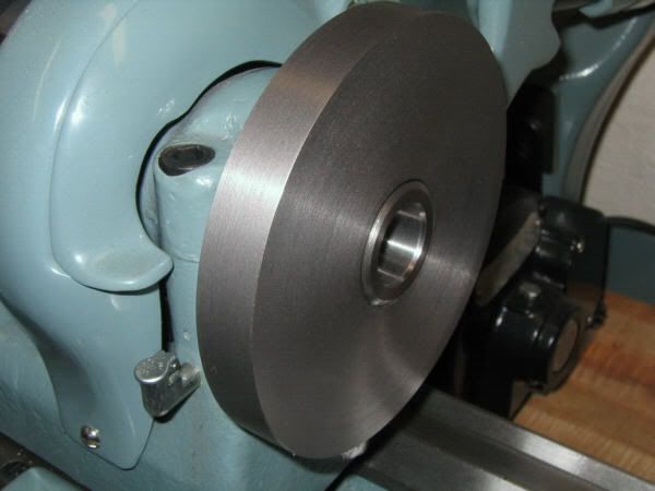
Notice that the chamfered end of the spindle protrudes slightly from the face of the plate, just as I had planned. I am still utilizing practically all of the available spindle thread, while reducing overhang to a minimum. The chuck’s scroll retainer plate will be counterbored slightly to clear this protrusion.
Now it was time to begin machining the shoulder that would align the adapter plate to the chuck. One needs to work carefully here, as the fit between the shoulder diameter and the I.D. of the chuck is important. Once you get close, take only light cuts to “sneak up” on the required diameter. Ideally, you want a zero clearance fit -- not a press-fit, but something closer than a slip-fit. I guaged the last couple of cuts by offering up the actual chuck to the machined shoulder.
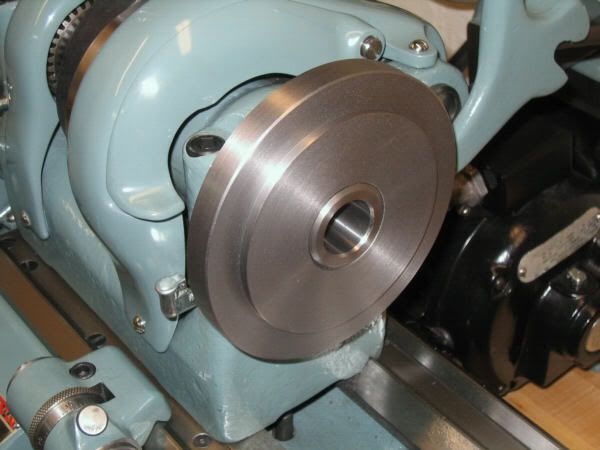
After machining the shoulder to the correct diameter and length, turn the O.D. of the plate to match the chuck’s O.D. This is not an absolute necessity, but it does look more professional. Also, try to get the chamfer on the adapter to match the chamfer on the back of the chuck. As a last step, chamfer the back side of the plate. Here’s the finished adapter plate, still in place on the spindle nose:
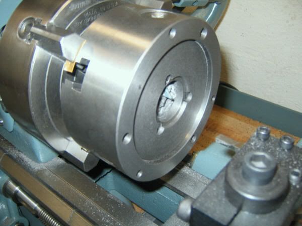
The only thing left to do (other than drilling and counterboring for the mounting screws), was to re-mount the 4-jaw and counterbore the back side of the 3-jaw chuck's scroll retainer to clear the end of the spindle thread. Here’s the finished job (notice the brass shims between the jaws and chuck body, and the paper towel stuffed into the center hole to keep chips out of the scroll):
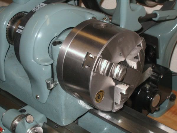
With that operation completed, I decided I wanted to see what the new chuck would look like mounted on the lathe spindle. While I still needed to drill and counterbore for the mounting screws, the fit between the adapter plate and chuck was tight enough that it would stay in place while I snapped a picture (Just keep that hand away from the motor switch!):
Since I don’t currently have a good, accurate way of locating and drilling the mounting holes, I will take this job to my friendly local machine shop. I’m sure they can take care of it in a jiffy.
Well, one more step completed toward finishing an almost year-long restoration job! I hope some of you found this useful or interesting.
Paula
My 9A lathe restoration project is almost done, but one accessory I wanted to add before the lathe can be considered complete is a good 3-jaw chuck. My lathe came with a very nice Skinner 6” 4-jaw chuck, which will get a lot of use, but a decent 3-jaw can be used for a lot of the less-demanding jobs, or those which can be finished in a single setup.
My first mistake was to purchase a used chuck. I DO NOT RECOMMEND THIS. You will likely wind up with the target of many years’ worth of abuse by previous owners. (By the way, if anyone’s interested in a decent anchor for their fishing boat, with a nifty built-in rope gripper, contact me off-line.) So with that lesson learned, I decided to purchase a new Bison 5” (125mm) 3-jaw chuck, with an unmachined, threaded adapter plate. The Bison is a Polish-made chuck, of decent quality and a good value. Not the best, but certainly not the worst, and just fine for occasional home-shop use.
I decided against the “direct mount” type because I wanted the chuck to run as true as possible on my lathe. Given the inherent inaccuracies of a scroll-type chuck, I figured it could use every break it could get. So, I purchased the bare chuck along with a rough-machined adapter plate, pre-threaded 1-1/2"-8 to fit the spindle nose of my lathe. This means that the seating face and shoulder which locate the chuck will be machined on the actual lathe that the chuck is to be mounted. This way, any irregularities of my particular spindle nose will be compensated for.
I tried not to include too many pictures, since I know how they can affect the loading time for those without high-speed connections. The first one is a cross-section that I did on the CAD system, to arrive at the desired mounting configuration. The lathe’s spindle nose is shown in red, a cross-section of the chuck body is shown in green, and the machined adapter plate is shown in blue. The original, unmachined outline of the of the adapter plate is shown in brown:
One of my goals was to reduce the overhang of the chuck to an absolute minimum. My theory is that every millimeter that the chuck sticks out past the end of the spindle bearing amplifies the effective bearing clearance, increasing the possibility of deflection and chatter at the workpiece. Therefore, you will notice that I tried to get the spindle nose to fit as close to the chuck as possible, even to the point of needing to counterbore the scroll retaining plate slightly to clear the tip of the spindle thread. One drawback to this configuration is that it slightly reduces the amount of workpiece clearance behind the jaws, but I figure the overhang issue trumps it. Another drawback is the amount of material that needs to be removed from the adapter plate’s hub! I toyed with the idea of setting this up on the saw somehow, but later decided that this is what automatic cross-feed is good for.
Since I was going to be modifying the hub, and this operation would affect the alignment of the plate to the spindle nose, it needed to be done before machining the registration surfaces for the chuck. The first step is to thread the adapter plate onto the spindle and take a skim cut on the face and O.D., to get these surfaces in alignment with the spindle thread:
NOTE: The swarf from machining cast iron is some nasty, gritty stuff. So I took steps, where practical, to catch the chips as they were produced. Also, after each phase of the machining process, I took the time to clean up and re-lubricate the lathe.
After machining the face and O.D. of the plate, I removed it from the spindle and mouned the 4-jaw chuck. The adapter plate was carefully centered in the 4-jaw so that the thread’s counterbore was in alignment with the lathe axis. Now I was ready to begin machining the hub:
I had to make quite a few chips getting the hub down to size! But even so, it didn’t seem to take that long. After facing the hub to the correct length, I used a stubby boring bit to counterbore the threads to the required I.D. and depth, along with a 30 degree lead-in. Also, since there was visible runout of the rear face of the adapter plate, I decided to take light, truing cut. This is not a functional surface, but I didn’t want to have to see that surface wobbling around every time I used the chuck. Here is what the completed hub-side of the plate looked like, removed from the spindle:
The next step was to remove the 4-jaw and thread the adapter plate back on the spindle:
Notice that the chamfered end of the spindle protrudes slightly from the face of the plate, just as I had planned. I am still utilizing practically all of the available spindle thread, while reducing overhang to a minimum. The chuck’s scroll retainer plate will be counterbored slightly to clear this protrusion.
Now it was time to begin machining the shoulder that would align the adapter plate to the chuck. One needs to work carefully here, as the fit between the shoulder diameter and the I.D. of the chuck is important. Once you get close, take only light cuts to “sneak up” on the required diameter. Ideally, you want a zero clearance fit -- not a press-fit, but something closer than a slip-fit. I guaged the last couple of cuts by offering up the actual chuck to the machined shoulder.
After machining the shoulder to the correct diameter and length, turn the O.D. of the plate to match the chuck’s O.D. This is not an absolute necessity, but it does look more professional. Also, try to get the chamfer on the adapter to match the chamfer on the back of the chuck. As a last step, chamfer the back side of the plate. Here’s the finished adapter plate, still in place on the spindle nose:
The only thing left to do (other than drilling and counterboring for the mounting screws), was to re-mount the 4-jaw and counterbore the back side of the 3-jaw chuck's scroll retainer to clear the end of the spindle thread. Here’s the finished job (notice the brass shims between the jaws and chuck body, and the paper towel stuffed into the center hole to keep chips out of the scroll):
With that operation completed, I decided I wanted to see what the new chuck would look like mounted on the lathe spindle. While I still needed to drill and counterbore for the mounting screws, the fit between the adapter plate and chuck was tight enough that it would stay in place while I snapped a picture (Just keep that hand away from the motor switch!):
Since I don’t currently have a good, accurate way of locating and drilling the mounting holes, I will take this job to my friendly local machine shop. I’m sure they can take care of it in a jiffy.
Well, one more step completed toward finishing an almost year-long restoration job! I hope some of you found this useful or interesting.
Paula