What's new
What's new

Machining the MLA-23 Toolpost

Paula

Titanium
Joined
Sep 16, 2005
Location
Indiana, USA
The MLA-23 Toolpost is the latest in a long line of machine accessory kits offered by Metal Lathe Accessories. While these kits are designed primarily for use with the South Bend 9”/10k lathes, some of the MLA accessories can be adapted for use with other brands and sizes of machinery. Having machined and used a number of MLA items, I can heartily attest to the high quality of materials and documentation.

The MLA-23 toolpost is of the “quick-change” type, designed to accommodate a variety of user-made tool holders, securely locked to an expanding dovetail tool block. This is an ideal project for the home-shop lathe user who enjoys the challenge/reward of making their own tools, and is looking to upgrade from the lantern-style toolpost.

With this thread, I will outline my experience in machining the MLA-23 toolpost. For those machinists contemplating making one for themselves, keep in mind that this treatise gives only one approach to the building process, and you are encouraged to apply your own skills as you see fit, the goal being to arrive at a result that satisfies your own individual tastes. A mill is not absolutely necessary to machine the toolpost, though it would no doubt make the job easier. I didn’t have one when I began the project, so I wound up using a South Bend milling attachment on my 9A lathe, enhanced with a South Bend shaper vise. (You can read more about it here.)

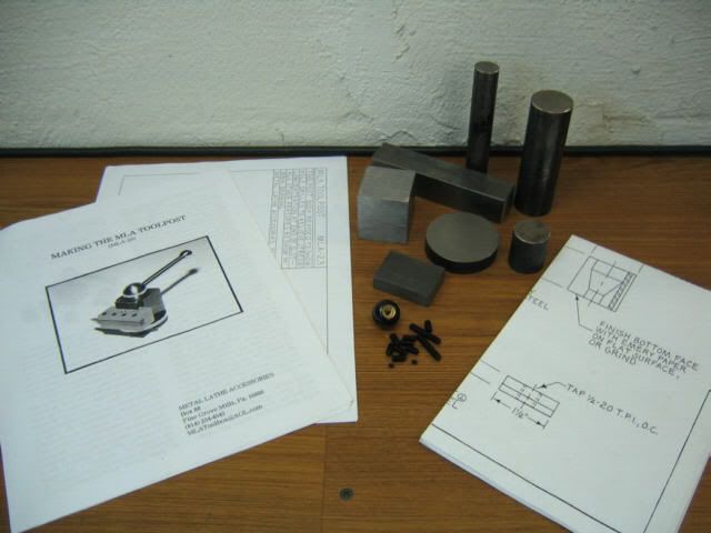
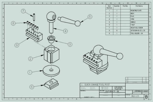
Unlike most of the MLA kits, the MLA-23 uses no castings. However, the kit includes all of the materials and hardware needed to complete the toolpost, along with excellent drawings and instructions:

KIT.jpg


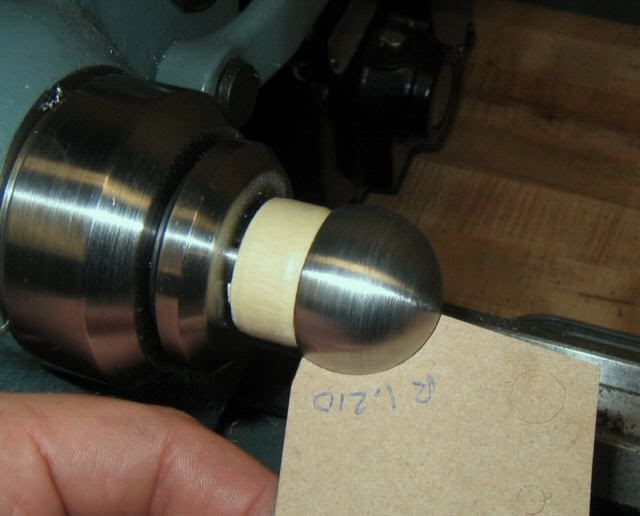
Mostly as an exercise, and just for the heck of it, I drew up the toolpost in Solid Edge (3D CAD system). Here’s a view of the assembly resulting from that effort (notice that I elected to use a tapered-style ball handle):

SE02.jpg


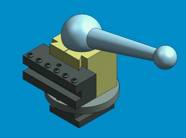
And here’s an exploded view, giving a clearer idea of how the toolpost is constructed:

SE01_640.jpg


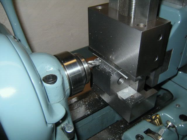
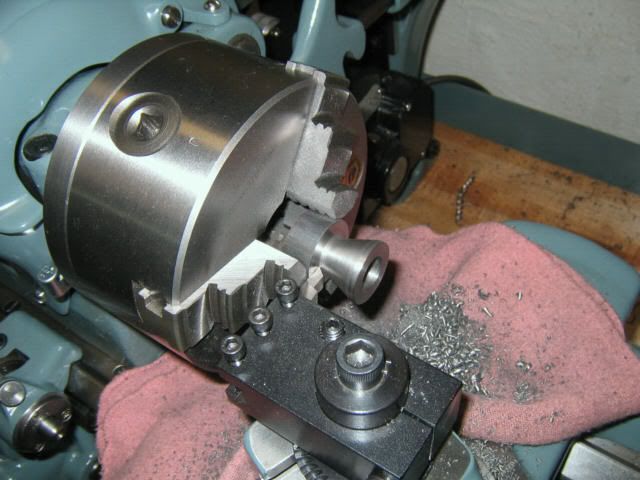
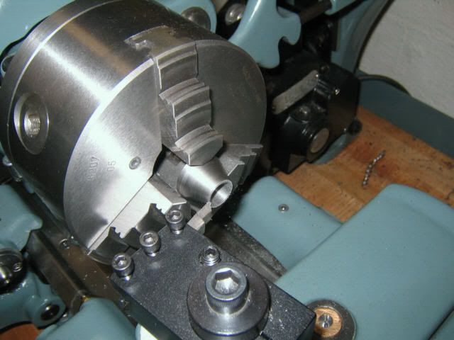
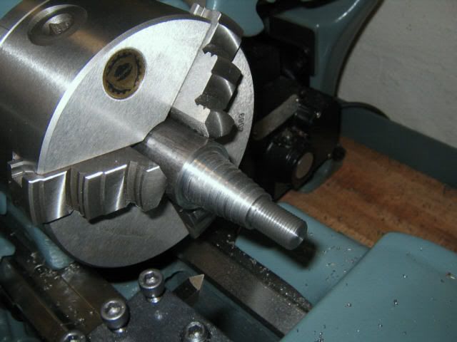
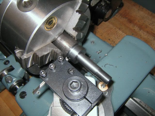
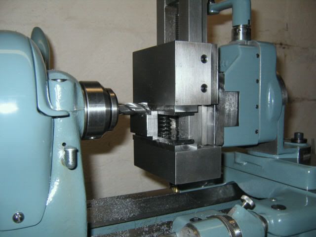
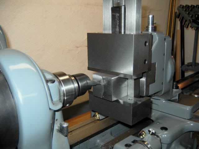
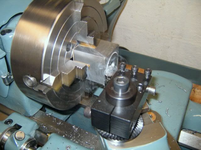
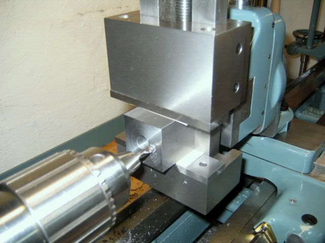
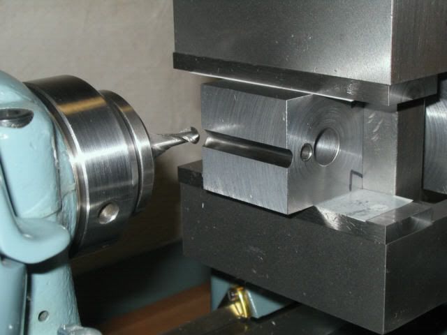
To get things off to an easy start, I began with the T-NUT. The kit includes a hunk of CRS for making this item. Though dimensions are included in the drawings, be sure to check the actual slot in your lathe’s compound to verify the correct size. Start by machining the overall size of the nut, and then notch the two corners as required:

TNUT03.jpg


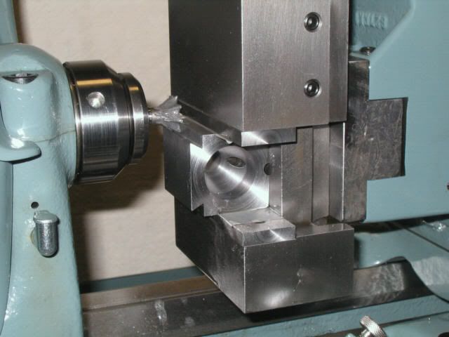
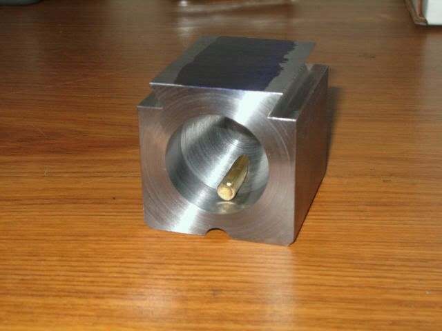
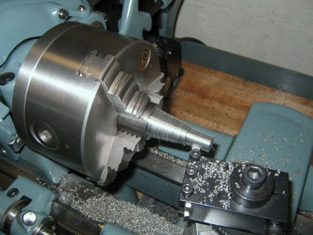
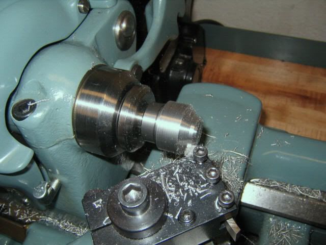
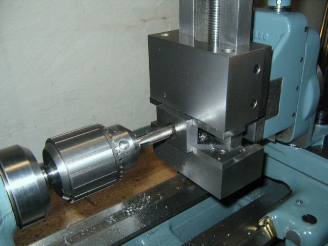
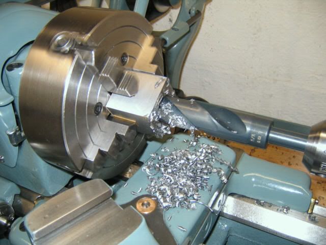
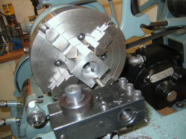
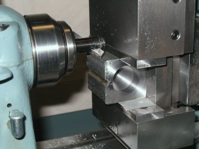
Finish off by drilling and tapping a 1/2-20 hole in the center of the nut:

TNUT05.jpg


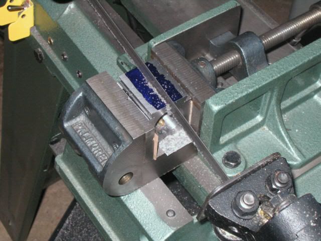
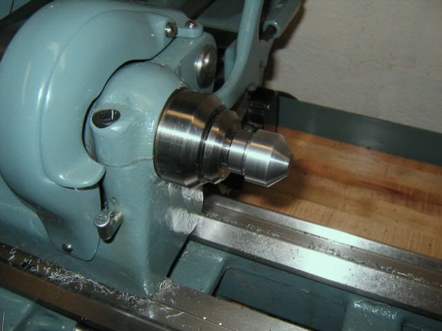
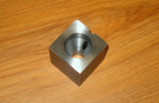
I put a black oxide finish on the completed T-nut.

(continued in next post...)
 
Probably the most complicated part to be machined is the BODY, for which a block of 4140 alloy steel is included in the kit. I began by squaring up the sides of the block and finishing it to size. A high-speed steel tool bit in a flycutter was used:

BODY01.jpg


The block was mounted in the 4-jaw chuck for drilling the thru-hole for the stem, and squaring the ends of the block to size:

BODY03.jpg


The block was mounted back in the milling vise to locate and drill the 3/16” stress-relief hole:

BODY04.jpg


With the block mounted back in the 4-jaw, I began roughing out the hole for the PLUG (a kind of wedge-shaped bushing) by drilling out the center hole with a large drill bit:

BODY05.jpg


A boring bar was used to finish the hole.

BODY08.jpg


A ball end mill was used to cut the external relief notch in the body:

BODY12.jpg


Though the design doesn’t call for it, I chamfered (2) of the corners with a flycutter, purely for appearance’sake:

BODY07.jpg


Here’s what the body should look like, at this point:

BODY17.jpg


(to be continued...)

ADDENDUM: This treatise will comprise a series of posts which are still in production. In the meantime, feel free to interject any comments or questions you may have -- no need to wait for all installments to be posted.
 
Last edited:
Hi Gary,

I presume you mean, do I know if axa size tool holders will fit this tool post. The answer is, I don't know, but I would be surprised if they did. At least, I don't recall any mention being made in the literature for this kit of any intentional compatibilities along those lines.

Paula
 
AAUGGHH! PAULA! You're getting CHIPS! And OIL! And... and STUFF on that pristinely restored machine!

Seriously, though, it looks like a good start on a nice project.
 
Ahh yes, Vraptor, there goes the museum-artifact status. :(

Really, I do like to keep it looking as "new" as possible, but that desire is balanced by the need to use it, and I have never shied away from doing so. Also, I have never hesitated to pursue non-original modifications/upgrades which improve its usefulness. It is a tool, after all. :)

Anyway, getting back to the MLA-23...

With the Body block mounted back in the milling vise, I began the dovetail machining process by using a standard milling cutter to remove most of the material required:

BODY27.jpg


A 60° dovetail end mill, and light cuts, were used to finish up the dovetails:

BODY25.jpg


With the dovetails machined to size, the Body is now ready for slitting. For this operation I decided to use my 4 x 6 cutoff bandsaw. I was a bit worried about the saw breaking thru the stress-relief hole and marking the opposite side, so I inserted a brass “plug” to catch the saw blade as it breakes through the steel (a small concern, but I thought it worthwhile):

BODY22.jpg


I used my drill press vise (removed from its base) to hold the Body for the slitting operation:

BODY28.jpg


After some careful deburring, the Body is now completed.

The next component that I machined was the PLUG. An appropriately-sized bar of cast iron is included in the kit to make this item. I chucked the cast iron bar in the 3-jaw chuck to drill the thru-hole and machine the outside contour of the part:

WEDGE06.jpg


While the part could be cut off in the lathe, I chose to remove it from the chuck and use the cutoff saw. Then I re-chucked the plug (using a piece of round stock in the tailstock to align the part in the chuck). There is very little cylindrical surface left on the plug for the jaws to seat on, so it's necessary to take a very light cuts to face the sawed end:

WEDGE04.jpg


This finishes the machining of the Plug.

(to be continued...)
 
PAULA

Nice writeup! Fun to "watch".

Think about using alu. foil to catch the CI swarf instead of the shop rag.
You will be glad you did in the event of a catch.

"Everyone's a critic" ;-)

CalG
 
Last edited by a moderator:
Paula

I am interested in knowing more about fly cutting the 4140 - could you post a pic of the HHS tool bit - like to see how it is shaped and tell me what spindle speed and depth of cut was used.

Thanks
Dennis
 
Hi Dennis,

I used a 5/16" square HSS tool bit which was originally ground as a standard lathe turning tool -- no special angles or grinds. It has a nose radius of approx. .030":

flycut001.jpg


It's been many months since that part was made, and I don't recall any specific speed/feed values, but I know that the depth of cut and feed rate would have been on the low side, given the substantial overhang of the setup. This was a case where I set the automatic cross feed, and just let the lathe do it's thing while I did something else.

Paula
 
Last edited:
The next part to be made is the handle STEM. I made this part slightly different from the MLA drawings, due to my re-design for the tapered handle, but it is functionally the same. A piece of round CRS is included in the kit for making this part.

The first step is to chuck the stock in the 3-jaw, leaving enough length sticking out to machine all but the ball end. To avoid the need for supporting the tail end with a center, the 1/2” shank can be turned in “steps”, which will give the needed support for threading the end:

STEM01.jpg


Here’s a veiw with the threading completed (you could also use a 1/2-20 threading die for this operation):

STEM03.jpg


Now we can go ahead and finish turning the 1/2" shank. A 1/8” round-nose bit was used to make the undercut just below where the spherical portion will be:

STEM04.jpg


At this point, the stem can be removed from the chuck. I elected to use a 1/2” collet to hold the shank of the stem for turning the spherical portion. Since I don’t presently own a ball-turning attachment, I needed to use a different method. Basically, the spherical portion is reduced to a series of angled, tangent surfaces, and once these have been turned, it’s a fairly simple matter to finish the profile by hand filing. Here’s a view as the 45° angle is being turned:

STEM06.jpg


And this is what it looks like just prior to finishing with a file:

STEM07.jpg


It’s a good idea to wrap some tape around the exposed finished areas of the part to prevent any unwanted file marks. I made up a custom cardboard radius gage to check progress as the spherical surface is taking shape. Here is what it looked like with the file-shaping completed – it doesn’t take that long, and isn’t as difficult as you might think. As long as the ball surface is decorative only, this method is almost quicker than digging out a radius attachment, setting it up, etc:

STEM09.jpg


After sanding with progressively finer grits of sandpaper (be sure to protect the lathe from grit), the stem can be removed from the lathe, and the ball surface finished with polishing wheels on the bench grinder:

STEM11.jpg


Here is what the handle stem looks like at this stage (threaded into the T-nut):

STEM13.jpg


It’s a good idea to defer facing, drilling, and tapping the stem ball for the handle until after the handle has been completed.

(to be continued...)
 
Paula:

Out of curiosity, why did you elect to use your lathe instead of your mill for the first stages of the project? Everyone slams the factory milling attachment and yet you put it to good use. I assume you still have your mill?
 
Hi WL,

Yes, I still have the SX3 mill, but I didn't have it when I began the toolpost project. By the time I got the mill, all I had left to make was the toolholders. The milling attachment is indeed a pale substitute for a true mill (or even a "mill drill"), but it's surprising what can be accomplished with a bit of patience and finesse.

Paula
 
Last edited:
...so I wound up using a South Bend milling attachment on my 9A lathe, enhanced with a South Bend shaper vise. (You can read more about it here.)

Paula,

Could you have made all the pieces for the tool post with the milling attachment alone? Was the main advantage of the vise its larger capacity?

Danny
 
Last edited by a moderator:
Could you have made all the pieces for the tool post with the milling attachment alone?

I suppose anything is possible, but I would not have attempted it.

Was the main advantage of the vise its larger capacity?

That, plus the fact that it is a vise. The SB milling attachment has only a fixed opening with two clamp screws. It also originally shipped with some loose clamping shoes, but they are not a lot of help.

Paula
 
milling attachment

Paula,
Great thread, thank you!
What kind of milling attachment did you use? And how did you attach it to the cross slide?
Thank you!
Tony
 
What kind of milling attachment did you use? And how did you attach it to the cross slide?

Hi Tony,

I used a South Bend milling attachment. It is attached to the cross slide with the same type dovetail-spigot is used by the compound slide. (See the third paragraph of the first post in this thread for more info.)

Paula
 
It doesn't appear as if the design allows for repeatably replacing tool holders. What prevents the tool post from rotating when the tool holder is unclamped?

Hi Chris,

You are correct -- this toolpost does not feature radial registration. Quite honestly, I have never seen the need for it. Perhaps with more production-oriented setups? I have used the Omni-Post (shown in the photos above) since the mid 1980's, which does have radial registration, and have yet to use it. In fact, that is one of the things I like about the MLA-23 design: it is not complicated by what I see as a superfluous feature.

Paula


Back
Top