What's new
What's new

math help needed for rpm

SE18

Cast Iron
Joined
Feb 13, 2012
Location
N. Virginia USA
HTRAL says the countershaft speed should be 255 rpm; however, my pullley size and motor rpm is different than that listed for the 9A, which I have. So I went to the Hercus book: "Textbook of Turning, chapt 10, pg 76, which states: The speed of the driven pulley equals the speed of the driving pulley times the diameter of the driving pulley divided by the diameter of the driving pulley.

First, the speed of the driving pulley should be exactly the speed of my GE motor, 1725 rpm.

I have a 2-pulley setup so each will be different.

First motor pulley:

1725 rpm (speed of driving) X 1.2 (driving diameter) / 10.2 (driven dia) = 203 rpm

2nd motor pulley:

1725 X 2.5 / 9.2 = 469 rpm

Next, I'm gonna calculate using same formula the 3 cones, cone 1 being left and 3 being to the right as you face the lathe.

cone 1 pulley 1: 203rpm of driving pulley x 5 (dia countershaft driving pulley) / 2.5 (dia driven on Headstock) = 406 rpm

cone 1 pulley 2: 469 x 5/.25 = 938 rpm

cone 2 pulley 1: 203 x 4.1/3.3=252

cone 2 pulley 2: 469 x 4.1/3.3=583

cone 3 pulley 1: 203x3.1/4.3=146

cone 3 pulley 2: 469x3.1/4.3=338

So is the math correct?

How would one determine those speeds with backgears engaged. I'm told that pulley 1, the slowest (203 rpm) should be the ONLY pulley used with backgears.

Thanks in advance

Dave V

PS, If the motor says 1725, is that really the RPM or does it slow over the years?

PS2, I suppose the backgears go so slowly I could put a magic marker tick on a cone and with stopwatch count the rpms

PS3, after the math is determine to be correct or not, I can calculate the fpm and then check what metal I'm using (aluminum 1" round) and do my first cut ever!!!!!
 
Your numbers look correct.

For backgear, divide everything by 5. If you use the higher speeds with backgear, it'll make a racket.

Motors should maintain their speed, regardless of age. The "1725" is determined by the power line frequency and the number of poles in the motor, neither of which is subject to change.

Yes, in backgear you can count the rpms.

No need to be so fastidious; pick a speed and go. I doubt that many of us are calculating surface fpm, it's more of a trial and error kind of thing.
 
thanks;

so backgear using pulley setup 1 (the slowest pulley from motor) would be the driven cones 1, 2, 3 divided by 5

cone 1 in backgear: 406/5 = 81 rpm
cone 2: 252/5= 50 rpm
cone 3: 146/5 = 29 rpm

I'll count them later just to check.

This is interesting. Each motor pulley gives me 3 speeds on the cones so that is a total of 6 speeds. And if I use the backgear in the slowest pulley that's an additional 3 speeds for a total of 9 speeds. I haven't used the QCGB, but when I do, I think that would add even more speeds. I may have question later on about that such as which motor pulley to use and whether or not to engage backgears.
 
thanks; is there a specific speed that you should not exceed when using backgears and is the racket they make not good?

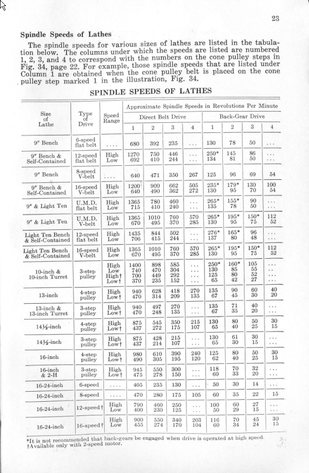
If you look at all the asterisks in the chart and the explanation at the bottom you'll have SB's answer to your question.

H2RunLathePg23.gif


Hope that helps to answer your question.

-Ron
 
Just to clarify something, South Bend model 9A lathe came in two basic versions, the standard flat belt Version and the V belt version.

The flat belt version has 3 cone pulleys Which provides 3 Speeds. each drive pulley must be used with the corresponding spindle pulley. for instance you have to go from pulley 1 on the drive pulley to pulley 1 on the spindle pulley. you cannot go from pulley 1 on the drive pulley to pulley 2 or 3 on the spindle pulley.
With the addition of back gear The speeds are double Giving a total of 6 Speeds. If you have a two speed motor pulley you double that number For a total of 12 Speeds.

The V belt version has 4 pulleys given 4 Speeds. With the addition of back gear The speeds are double Giving a total of 8 Speeds. If you have a two speed motor pulley you double that number For a total of 16 Speeds.

also The recommended feet per minute number is only a reference. It is very difficult to get the exact feet per minute when your Are turning something in the lathe. The biggest problem is every time you take a cut you change the surface fee per minute.

A good indicator that you're going too fast this if your Chips are changing colors. this would indicate that your tool is getting too hot. When your tool gets too hot, the cutting-edge will dull quickly and create more heat. It is a progressive action.

if your chips are changing colors stop the cut, Inspect the tool and make sure it's Sharp. If it is still sharp, reduce your speed.

Note: if your lathe is equipped with a VFD, you can closely match the feet per minute recommendation but in order to maintain it you will have to I just your VFD for each new cut. but it is not that critical.
 
The QCGB won't change the spindle speed, it only affects the leadscrew. You'll be using backgear primarily to turn large diameter parts that require lots of torque, and for coarse threading.
 
The recommended (CS) cutting speed for machinig mild steel is 100 feet per minute. Softer steel like 12L14 is 150 feet per minute. Harder steel like Stressproof is 75 feet per minute. ( FORMULA TO DETERMINE RPM = four times the (CS) cutting speed divided by the diameter.) To machine a 1 inch diameter piece of mild steel would take 400 rpm. To machine a 1 inch diameter piece of 12L14 would take 600 rpm. To machine a 1 inch diameter piece of Stressproof would take 300 rpm. These cutting speeds are recommended for high speed steel tooling. Also applies to drilling with HSS drills.

Lord Byron
 
Cone 1 pulley 1
Predicted:
Backgear 406/5 = 81 rpm
Observed:
127 rpm

Cone 2 pulley 1
Predicted:
Backgear 252/5 = 50rpm
Observed:
73 rpm

Cone 3 pulley 1
Predicted:
Backgear 146/5 = 29 rpm
Observed:
45 rpm

All of the math was checked and double checked. A non-stretch string was used to measure the circumference of each pulley and each cone and then stretched out and measured with a ruler. The circumference was then divided by pi (3.14) to obtain diameter.

Seems to me observed is more reliable than the math as I actually counted the tag on the spindle face as it spun around. I video-taped it and double-checked the time of the video with a stop watch for 60 seconds.

So what went wrong (obtained vs. predicted)?

I don’t have a clue.

What should I do?

Besides investing in a speedometer, I think the easiest thing to do is to reverse the math and multiply each backgear speed by five. That would at least give me the speeds on the first motor pulley. On the second motor pulley, I’m afraid I’d lose count as counting to 127 for cone #1 was all the effort I could muster.

Unless, of course, I only measured the rpm of motor pulley #2 on the 3rd cone and somehow calculated the speed ratios of cones 1 and 2.

Hope I didn’t lose anyone.

I could post the vids if that would help.

Thanks!

BTW, thx for tips including that really neat online calendar, which is now bookmarked
 
OK, to add to my observations, I just connected motor pulley #2 and tested out the slowest cone, which is #3.

Observed speed is 83 rpm, per video observation of 60 seconds.

From the 3 cone speeds on motor pulley #1 and this speed on pulley #2, I should be able to deduce the speeds of pulley #2 cones 1 and 2.

I have to call my daughter to see how that's done as she majored in math (math gene skipped 2 generations in my family)

remember, all these observed speeds are in backgear so I suppose I could multiply each by 5 to get non-backgear speeds if that calculation holds
 
Did you ever check the RPM of the drive pulley? Even though it's speed is listed at 1725 rpm there is a good possibility that it's no longer correct. That speed rating was using a 60 Hz supply whereas your "modern" power may differ from that.

-Ron
 
When calculating drive ratios of v-belts the outside diameter of the pulley is used, not the diameter at bottom of the vee.
So your string measuring is likely the problem.
 
I don’t have a clue.

What should I do?

I'd say move on and start making some chips. Once you begin making stuff, you'll pick your speeds by what "feels" right. Just keep your spindle speed under 1000 rpms or so, to be kind to the bearings.
 
ok then chips it is

still, for ballpark, gonna take the backgear measures and multiply by 5 so I kind of have an idea. At least those rpms are confirmed!

don't you get tired of beginner questions?! LOL
 
Actually, the hope is that at some point, you'll be the guy answering the questions, rather than asking them ;).
 
So what went wrong (obtained vs. predicted)? I don’t have a clue.

I'm not sure what the formula (for back-gear) is, but it changes for each machine. I'm guessing the reason for THAT is due to different back-gear sizes, number of teeth, etc...

I just created a REGULAR spindle RPM spreadsheet for my 13" and it worked out almost perfect. Using the picture "MetalCarnage" posted, I determined the BACK-GEAR formula to be 14.41% (on average). I got this by dividing the back-gear RPM, by the regular spindle speed.

So for example:

a 13" lathe has a top speed of 940 on the fastest pulley. It's corresponding BACK-GEAR speed is 135.

135 / 940 = 0.1436 (or 14.36%)

That's what I used. Eventually, I'll be running a VFD so I'll be able to get those "in between" speeds to dial in the perfect RPM's. A tachometer would be a really nice addition as well.
 
that throws all my rpms in disarray then except backgear b/c I used the 1:5 formula on my 9A, meaning for every rpm of each cone in backgear, it will be 5 rpm's for that cone when not in backgear.

So far, to be honest, I've just been ballparking everything and not really counting; for turning aluminum, been using higher speeds, for parting and boring, been using backgear slow. I'm sort of listening to the lathe and trying to get a feel for it as someone recommended in this post earlier.


Back
Top