Hello to all! I have a new to me 1937 SB 9a that I purchased from the grandson of the original owner. This old lathe has been used very little and was well maintained. The only downside was that during a clean up and repaint, the old motor was found to be too far gone to feasibly be put back in service. I just purchased a new Century motor and would like to use the drum switch. Could anyone help, please? Tim
How to install the app on iOS
Follow along with the video below to see how to install our site as a web app on your home screen.
Note: This feature may not be available in some browsers.
Largest Manufacturing Technology Community on the Web
Stay Connected:
You are using an out of date browser. It may not display this or other websites correctly.
You should upgrade or use an alternative browser.
You should upgrade or use an alternative browser.
Need some help wiring my new Century C311 and a Furnas R1 drum switch, Please.
- Thread starter Rd2nowr
- Start date
- Replies 16
- Views 4,221
kitno455
Titanium
- Joined
- Jul 9, 2010
- Location
- Virginia, USA
We need pictures of the wiring diagram on the motor and the switch, and possibly a picture of the guts of the switch too.
allan
allan
kitno455
Titanium
- Joined
- Jul 9, 2010
- Location
- Virginia, USA
Oh, and do you want 110 or 220 volt?
allan
allan
kitno455
Titanium
- Joined
- Jul 9, 2010
- Location
- Virginia, USA
Well, I poked around online and found a picture of a motor and switch diagram. I'd still like to see pictures of yours to be sure, but these drawings will work for what I found.
110 volt:
220 volt:
allan
110 volt:
220 volt:
allan
Well, I poked around online and found a picture of a motor and switch diagram. I'd still like to see pictures of yours to be sure, but these drawings will work for what I found.
110 volt: View attachment 195098
220 volt: View attachment 195099
allan
That's got it, Allen! I connected the Blue wires from the motor to the 1 position on the switch.
kitno455
Titanium
- Joined
- Jul 9, 2010
- Location
- Virginia, USA
I numbered the terminals on the switch, but it really does not matter. You could turn the switch 180 degrees in the drawing (putting the handle at the other end) and it would still work, because the switch layout is symmetrical. Does that answer your question?
If the motor rotates backwards from what you want, switch the black and red wires.
Again, this is predicated on your equipment matching the images I found online. Caveat lector.
allan
If the motor rotates backwards from what you want, switch the black and red wires.
Again, this is predicated on your equipment matching the images I found online. Caveat lector.
allan
kleppermaster
Plastic
- Joined
- Jan 21, 2008
- Location
- Madison, WI
Furnas R22 to Century C310?
I'm a newbe to this web site too. I just acquired a SB 9A and would like to use a Century Electric model C310 motor with a Furnas R22 drum switch. I was just wondering if the wiring layout you posted is the same for the C310.
My C310 has a overload reset switch (ORS) in it. The yellow with black lead goes to the ORS. A brown lead and a Blue lead exit the ORS. The Brown lead joins a yellow lead on one side of the centrifugal switch (CS). The other side of the CS is at Lug4 where there is a Red lead connected that leads to the Starting Capacitor. I assume the other lead of the starting cap goes to the start winding.
There is a Black lead that is connected to Lug6. If you switch the black lead with the red lead the motor runs in the opposite direction. I suspect the black lead is the other end of the start winding.
Also, Lug6 is one of the main lines
The yellow & black wire is connected to the other main line.
Before I mentioned there is a Blue lead that comes out of the ORS. This blue lead dives into the Stator windings I suspect it is one end of the run winding.
I have pictures, but have not yet learned how to add them to a post yet.
Attachments


kleppermaster
Plastic
- Joined
- Jan 21, 2008
- Location
- Madison, WI
Oh, I guess I do know how. There they are.
kitno455
Titanium
- Joined
- Jul 9, 2010
- Location
- Virginia, USA
Man, I hate this kind of motor. It's difficult to tell if you are doing something dumb like accidentally bypassing the starting cap. And, the original poster did not help much by never showing any pictures, and asking questions about a blue wire that is not even on the diagram, then just assuming he knew where to connect it.
You can certainly try the diagram I gave, but without knowing what is behind each of the lugs on that terminal board, I'm not sure I would trust it.
allan
You can certainly try the diagram I gave, but without knowing what is behind each of the lugs on that terminal board, I'm not sure I would trust it.
allan
kleppermaster
Plastic
- Joined
- Jan 21, 2008
- Location
- Madison, WI
Allan,
Thanks for the reply!
I have looked behind the terminal board & this is what I can remember:
The terminal board has 6 lug locations.
All lugs except 4 & 5 have no connections on the back side of the terminal board.
Lug 1 (with the yellow & black lead)is one of the line lugs. This is the complicated line lug that supplies power to the start winding and the run winding through the overload switch.
Lug 2 is not used
Lug 3 is unused for low voltage operation.
Lug 5 (with the brown lead and orange lead) is connected to one end of the centrifugal switch.
Lug 4 (with the red lead going to the starting cap) is connected to the other end of the centrifugal switch.
Lug 6 is one of the line lugs and everything comes home here.
I can pull the end off the motor and take some more pictures if that would help.
kleppermaster
Plastic
- Joined
- Jan 21, 2008
- Location
- Madison, WI
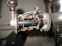
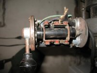
Here are some more pictures showing the inside under the end cap.


kleppermaster
Plastic
- Joined
- Jan 21, 2008
- Location
- Madison, WI
If I had a 3 pole triple throw (center position open) drum switch this wiring problem would be easy.
The attached picture is a schematic of how it could be done.
To switch the century C310 from forward to reverse one simply interchanges the black line (normally connected to L6) with the red line (normally connected to L4)
The black line red line switch could be accomplished with a double pole triple throw switch. The third pole is to supply power to the run winding(s).
See the picture and let me know what you think.
kleppermaster
Plastic
- Joined
- Jan 21, 2008
- Location
- Madison, WI
Hey,
I took my Furnas R22 apart and I think I can modify it to match the switch pattern in the above schematic. The rotor contacts on the switch are the same diameter of a 1-inch copper pipe cap. To do this I must cut the existing contacts down so they only contact the end stator contacts. Then add another rotor contact cut to align with the middle contacts. This middle rotor can be fabricated from a 1-inch copper pipe cap by drilling (and filing) a 3/8 inch square hole in the end. Then cutting the sides to match the existing rotor contacts. The spacer between the existing rotor contacts can be cut into two pieces and the new contact installed between them.
However, I don't want to destroy my R22 before I'm sure the above circuit will work. Therefore, I plan to run an experiment first to verify my circuit.
kleppermaster
Plastic
- Joined
- Jan 21, 2008
- Location
- Madison, WI
OOPS! Silly me!
The circuit I showed will work if I had a 3 pole triple throw switch like the one in the schematic. However, There is no center tap on my drum switch so the circuit will not work.
I just acquired another drum switch with a different switch pattern. I think it will work better than the R22
The circuit I showed will work if I had a 3 pole triple throw switch like the one in the schematic. However, There is no center tap on my drum switch so the circuit will not work.
I just acquired another drum switch with a different switch pattern. I think it will work better than the R22
kleppermaster
Plastic
- Joined
- Jan 21, 2008
- Location
- Madison, WI

 Here are some pictures of the new switch internal connections and the schematic I have found on the inter web.
I have traced it all through and something is strange (either me or everyone out there that uses this switch.I suspect me). If someone can explain where I am going wrong I would be truly thankful!
The thing is it seem this schematic switches the polarity of the run winding(s) not the start winding(s).
Let's say L1 is hot & L2 is neutral.
With the switch to the left:
Run winding:
L1 connects from Lug6 which bridges to Lug5. Lug3 & lug5 are permanently connected. Next it travels from Lug3 to Lug4 where it enters the Run winding clockwise. The other end of the run winding is connected to lug1. From lug1 it finishes up at lug2 whites is L2
Start winding:
L1 connects to lug6 which bridges to lug5 where it enters the start winding counterclockwise. It passes through the start winding, captor & switch and ends up at lug2 which is L2
With to the right:
Run winding:
L1 connects from Lug6 which bridges to Lug5. Lug3 & lug5 are permanently connected. Next it jumps from Lug3 to lug1 where it enters the run winding counter-clockwise. The other end of the run winding is at lug4 which is switch connected to lug2.
Start winding: It follows exactly the same path counterclockwise as in the left mode.
L1 connects to lug6 which bridges to lug5 where it enters the start winding counterclockwise. It passes through the start winding, captor & switch and ends up at lug2 which is L2
kleppermaster
Plastic
- Joined
- Jan 21, 2008
- Location
- Madison, WI
I got it figured out.
Using the above switch I was able to get my C310 running both forward and reverse. The breakthrough was just forget switching the neutral wire. It's best to use a safety switch anyway. I will wire a safety switch in between the drum switch and the wall outlet. then if there is a power failure when it running I can walk away without worrying if it will start up again when power resumes.
Here is how I did it:
The switch has 6 contacts. If you look at the switch from the top there are 3 rows and 2 columns. The contacts are numbered first row ( 1,2) then second row (2,3)than the last row (4,5).
In reverse 1 connects to 2, 3 connects to 4, & 5 connects to 6
In forward i connects to 3, 2 connects to 4, & 5 connects to 6
Contacts 5 and 6 are good for switching the motor on and off because they switch the same way weather forward or reverse. To connect the hot line to contact 5. Then connect lug 6 on the motor terminal board (MTB)to contact 6.
Connect MTB lug 4 to switch contact 1
Connect MTB lug 6 to switch contact 4. But wait, you already connected MTB lug 6 to contact 6 so just jumper contacts 4 & 6.
In order to reverse direction the motor cover plate says to remove the black wire from lug 6 and the red wire from lug 4. Then connect the red wire to lug 6 and the black wire to lug 4.
So if you connect the black wire to the switch contact 3 and the red wire to switch contact 2. When the switch in reverse, the red wire will connect to MTB lug 1 and the black wire will connect to MTB lug 6
In forward, the red wire will connect to MTB lug 6 and the black wire will connect to MTB lug 4
It works!
Similar threads
- Replies
- 12
- Views
- 1K
- Replies
- 30
- Views
- 4K
- Replies
- 10
- Views
- 976
- Replies
- 5
- Views
- 2K