What's new
What's new

New member, New South Bend Model O

KB2WYL

Plastic
Joined
Apr 24, 2017
Location
Ferndale, CA
Hi all. Name here is Loren, and I'm in Ferndale CA. I've been looking at threads all over this site for a while now, as I searched locally to find my first lathe. Not too much comes up for sale here, especially if you're looking for a "compact", real machine (my requirements were like the "for sale" forum, no HF or....). Well, few days ago I got a hit from someone little over 3 hours away. Not bad, I can get there and back in a day. I've had a few of these replies, but this time the price was right: $450. All working, but he never used it. From what I can find, it's a model "O", correct?

Well, I'd love to knwo what some of you think. Good deal? What should I check for first? Those sorts of things.

Thanks all, look forward to being a member here,

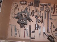
LorenLathe 001.jpgLathe 003.jpgLathe 008.jpgLathe 011.jpgLathe 012.jpg
 
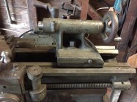
Series O. Based on the square gearbox profile and the small handwheel, likely a 9". Based on the shape of the headstock, 1929-1935 or so. The binding lever on top of the tailstock is from the latter end of that range. The tailstock in particular is a curiosity for me- it looks longer than normal (more stroke is a good thing in this case). All the missing gear guards and covers are unfortunate, but it looks like a good deal at that price anyway.

allan
 
KB2WYL,

Welcome to the forum. Inspect the ways for wear, specifically a groove on the way that is most directly visible when looking straight at the lathe. Look over every gear and inspect for broken or chipped teeth. Run the machine in each gear and listen for roaring bearings or any unusual noises.

Make sure the half nuts engage and check the auto feeds to make sure they work.

If it seems at all usable I'd jump on it. The steady rest alone is probably worth $200+, and the follow rest $150 so you really can't go wrong.

73 de N5STU
 
Very nice machine...great deal for that price..looks more like 800 to $1500 (on a very good day $2,000)

QT: [What should I check for first?]
Check oil is draining into spindle at both ends. Pick chips out of change gears, lead screw, back gears... Be sure thread half nut is engaging. Check the chuck jaws are numbered. if not and it runs close then add your own numbers perhaps with a Dremel grinder. *Don't spray clean machine with WD .. but wipe down with rag of thinner and a bit of oil. Yes try to find a safe cleaner. Water base cleaners are not so good IMHO. When clean drip can oil all the moving parts..oil rag wipe all the accessories.

Next a 2x2 pry-up under the chuck to see perhaps less than .003.. *but don't tear down the head with not reading up and asking a few questions.

Yes if not a lathe guy you might pick Thread Cutting by South Bend. you can free down load How to Run a lathe,

With having children in house and even with not you should fabricate or find a cover for head end gears..they chew small fingers. Perhaps mount the start switch high out of children reach. Teenagers in house add a key switch.

Don't see a 4jaw.. If finding you are a lathe guy pick up a good quality 4 jaw..Not some used crapped one...or a $100 import..
Buck
 
Thanks Johh, Allan. Yeah, the first I thought it was an "O" was through a pic that came up on a search, of another members Model O restoration, here on the forums. At some point I will surely take on this endeavor as well, but for now I'm going to place importance on just getting it back to complete working condition. Of course, I noticed the missing covers as well, and I'm sure there are a number of smaller things. Some of it I can fabricate, like the missing tool post collar and rocker base (it does have the post itself), using my mill. Other things, like the covers, will be on the collecting list.

Wow, John, down to 2 TPI! I'll be looking forward to finding out. Those would be some serious threads...What is the lower limit in the later models?

Allan, I didn't notice that until reading your mention of it, but yes that tailstock looks like it may be longer. Some of the pictures of the other Model Os I found look pretty close...And, for my eyes at least, its a bit of an optical illusion with the quill sticking out like it is. But I'm certain you're correct because the tailstock casting differences. All the other pictures I see, are identical castings. On this one though, it seems to extend further towards center. And, if you look closely at the back (outermost) vertical support of the casting, you can see where mine meets the base is a bit of a "triangle" pillar, where as the others are all just a "pillar" the same as the front support.

Well, leaving now for the haul up to get it. I've learned if you don't jump on opportunities like this....

Thanks again, looking forward to hearing more,

Loren
 
When you get the lathe home and cleaned up, you might want to build a better bench for it.
 
When you get the lathe home and cleaned up, you might want to build a better bench for it.


If not home be darn sure you don't tip it over. What a shame how many lathes are tipped over.
If that bench floor is solid might bolt it to some 4x4s.. bolt it to a heavy pallet.
Just rolling across the floor and hitting a bump in the floor can tip it over
 
The reason later Southbends did not have a 2 thread per inch settings is when you go that low with a 4 thread per inch lead screw it will break gears unless you are cutting plastic.
 
Thanks Guys. Just got it home and set in Garage. I will build a better table, but for now just going to hook it up (and fabricate a tensioner, which it did not have). Have to do that, he obviously knew even less than I and planned on loosening and tightening the bracket bolts every time he was going to change spindle speeds ha ha. Everything seems to be fine, visually, no broken or chipped teeth. No stuck, or sticky spots, though it does need cleaned for sure before any real use. Plenty of mismatched set screws and holding screws, that sort of thing, but not too bad for what it cost! I'll report back soon, sure I'll have plenty of questions....

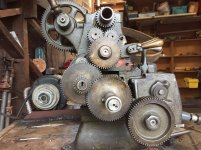
To start with, just two. I see I can adjust the (tumble gears? right?) You can see in the picture they are only making about half contact, I know they shouldn't be tight (for what it's worth, I do have some mechanical background), but what kind of tolerance am I looking for here?

Next is the micrometer dial for the cross slide. Is there anywhere to get one, besides a high priced E-bay sale? Or should I just put a spacer in there, until I make one with the lathe when it's running?

Thanks Guys!

Loren
KB2WYLIMG_2876.jpgIMG_2877.jpgIMG_2878.jpg
 
Found the micrometer dial...its on the gearbox tumbler lever...Must have been some job that the tumbler handle not returning too far from the spring, was more important than the cross slide having measurement indication...

And I was wrong about the gears, one tooth snuck by my initial look...The larger gear on the reduction countershaft, I believe that's called the Quill Gear? So, I'll have to look for that, or maybe just weld and file it back into existence.

For starters it won't be an issue anyhow, as I'll be doing smaller things and I'm sure I can get it down pretty darned low already the way it's set up.

So aside from the gears question, just one other one and then I'll stop for now...

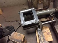
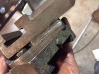
This Square Head bolt, in the compound rest swivel in the picture, what is this for? It looks like, checking it out from the bottom, something other than the compund rest top can be attatched, and then this bolt would hold it tight? I can see in there, but of course right now the square head bolt has no effect on anything...

Thanks again guys, really, this is great to be learning. And yes I'm checking out all the links and I have verified everything (as being OK and working) that's been said so far, with exception to the runout of the spindle.


Loren
KB2WYL
 
The square headed screw protruding from the top of the right saddle wing is a carriage lock. It pulls up on a little shoe that clamps against the underside of the bedway.

With a leather belt of longer length than yours, you actually can shift it between pulleys while its moving, using a wooden stick. That short, I'm not so sure.

allan
 
I:'m sorry, the pictures didn't post and I didn't notice til this morning. I'm on the way out the door to Welding classes up at the local CC (Started a year ago, figured I might as well get some certificates if I'm going to be doing it). The Square head I was talking about is this one:

IMG_2880.jpg

I can see where what it affects, attaches in this slot:

IMG_2881.jpg

So, I was just curious if I was missing anything. Looking through the manuals and guides, that doesn't appear to be the case to me, but I haven't yet found exactly what it is for.


One other thing that popped up last night was the issue of these hand wheels. Seems that originally South Bend used a screw straight through them and into the shafts, with a taper pin through the side and into the shaft to keep them from backing out. I've found that there were a few variations, of course. In either case, mine have been removed (and same goes for the knob on the tumbler lever). It seems like they were put back on using a pin all the way through the shaft. On each side of the hand wheel, I can see hammered pin tops, that are just about flush with the wheel. There is one that is barely sticking out, but it was not backing out with a good amount of force. So either someone used taper pins on both sides of the hand wheel, or someone put a pin straight through it and mushroomed both sides. There is no screw entering from the front of the hand wheel, just these pins (same on lever knob). Especially with the one on the cross slide, I don't want to be hammering to try to get that pin out. So I think I'll try grinding down one of the sides to completely flush, and then tapping out from that side. I'm sure you've seen this before...

Alright, off to school. Thanks so much for all the replies. Oh, and the belt, yeah that's another post but all of that will be re-done, the right way.

Loren
KB2WYL
 
The square head screw you are talking about is only there to keep crud out of the hole. The hole is to attach a thread stop. (A device used to make threading easier.) A thread stop is not needed to thread.
 
Nearly every pin on this machine is going to be a taper pin originally. If you cannot tell the big end from the small end now, due to deformation or modification, I'd ask myself if I really need to remove that handle...

allan
 
Thank you Gary, now I see how that works.

Alan, all the way through, they are taper pins? That sure makes more sense, seems I found reference to two small ones, one from either side, when I was searching yesterday...must have been someone else dealing with "mods".

As for asking whether I need to take them off, I believe I do. The micrometer dial being used as a spacer, I don't imagine that it is the exact right length...I know, for the tumbler lever, as long as it's pin goes in the hole for that gear, snug, you're OK. But set up like this the pin just goes in; The micrometer dial stops it from reaching enough taper to snug up. I'm pretty sure that would be ok, I mean it's enough to hold the tumbler in place like it's supposed to. But, that's one more thing to rattle.

As for the Cross slide, the situation is even more grim. Without that micrometer dial my free play is about 3 full turns of the handle! Backlash has got to be in the 1/8" area. No good. I'm not too concerned about the aesthetics for now (that handle has obviously been welded back together..twice..), but operationally I would like to have everything at least as tightly toleranced as I can.

So the way I see it (and please tell me if you think otherwise), is that I **at least need to fix the cross slide**. This means I have to get the handle off. Then, I either need to make a spacer, buy a micrometer dial, or retrieve the original micrometer dial from the lever.

I haven't found any for sale (that aren't more beat up than my misused one), I can't make one without one being there, so...


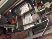
Today in class, I decided to make a tensioner for the flat belt system. I made sure that it would work even with my extremely short belt (Yes, I'm going to get a longer one like I should have), as well as in the future when I do get a longer one. The only advantage of having the whole counter-pully homebrew thing so close to the machine for now, is that I can hang some sort of gear guards off of it. Kids, all teenagers, but there's no reason not to shield the gears.

Here's a few pics of the tensioner. Either spring, or counterweight, to keep it. What do you guys think? My welding instructor (who's actually a machine shop inspector as well), said to just give it enough force either way to keep the belt taught, as if you were only placing the weight of your arm across it.
IMG_2882.jpgIMG_2883.jpgIMG_2884.jpgIMG_2885.jpgIMG_2886.jpg


Loren
KB2WYL
 
In your third picture of the gear train gears not meshing it is a simple adjustment to close the gap between the gears. Simply loosen the bolts on both ends of the arm (called a banjo on newer 9" SBs) and rotate it to adjust the gap.
 
Thank you Tommy. I had seen that, and generally I know what type of tolerance mesh gears like this like, but I was asking what the specific tolerances are in these lathes. Obviously they're too far now, and snug together is too tight, what is the correct tolerance gap?

I got the micrometer off of the tumbler handle, and put it where it belongs on the cross slide handle. The taper pin in the cross slide handle was a pain, but I got it without drilling. The one on the tumbler handle was a little larger, and came out easily.

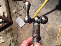
The shaft that the tumbler lever rides on. To remove the lever, of course you have to remove the shaft. The outside bushing race, I see it has a key way. What is this keyway for? I see there are threads for a set screw, but obviously you can't key that shaft to the casting so??

IMG_2887.jpg

With the micrometer dial back on...before, I had 3 turns of play. Now, I still have 1/2 turn, a bit too much. Is it usually more the threads in the drive nut, or equally that and the acme screw? I see many of the nuts, new, for sale...

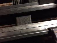
Here's a couple more pics. The cross slide with the micrometer (yes, I used a bolt. No, I did not drill it out, bolt was snug) And the bed ways. Though there are some dents in the crowns, thankfully the races are not scored.


IMG_2889.jpgIMG_2890.jpg

Thanks all,

Loren
KB2WYL
 
That keyway is not for a key at all. It is for a felt oiler. It gets oiled through the banjo that would be in alignment with the hole. Sometimes a groove is cut in the banjo to allow oil get to that hole. People plumb the oil to the felt differently and all these machines are not identical. That 66 tooth wide gear on that end of the shaft comes off easily when you remove the nut holding it on. Take that banjo off and you will see the oil hole. The set screw holds the banjo on the gearbox. The threaded hole that has nothing in it is the oil hole for the felt usually a small pipe or Gits oiler installed.


Back
Top