What's new
What's new

South Bend Nameplate Font Choices

thomasutley

Hot Rolled
Joined
Sep 10, 2014
Location
Oro Valley
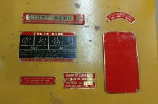
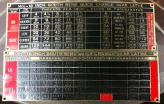
I'm in the process of etching replacement brass nameplates and switch legends for my 1943 16" lathe. So far for parts like the War Board tag, the Catalog No./Swing tag, etc., I've gotten away using a condensed variant of Franklin Gothic using minor Inkscape manipulation to control kerning and word spacing. However, the gearbox threading chart seems to be a completely different animal, with unique typographic features especially in the S and Q characters, that does not fit well with the Franklin Gothic family.

The "Grotesk" font family is close, and Helvetica comes close in other respects, but neither is quite right for the S and Q which are so prominent on the top line of this plate.

Has anyone here had better results searching for a matching font on their own etched plates? Seems like SBL Co. would not have had a very wide field from which to choose in the 1940s for industrial labels, or am I assuming too much and it could be anything or even custom designed in-house?

I would love to understand the process they used for making etching masks back then.

Thanks,

Tom

South Bend 16 Gearbox Threading Chart.jpg
 
I don't know the first thing about etching. As a pure guess I was thinking the plates were pressed under high pressure to get the raised lettering, as well as the shape of the edges.

I had begun attempting my restore of data plates just prior to making my machine operational. In fact I made a slight push to do so. I feared if I got the machine running, I may not return to the plates, lol. I got several done, but it was very time consuming, probably spent 3 days on them. Basically cleaned them, then polished the raised areas, then painted. But in some cases I was taping off individual words, and/or painting each plate in various sections over a few days. I did not have luck on the lube chart as the words were too thin from peoples hands or elbows I guess.

I got about half way into quick change plate, and abruptly put all plate work on hold, it was just eating up too much time. Though the plates I finished really look great on machine imo. They have that original look, with some dings, but look clean and fresh, the look really does it for me.

Anyhow, I had a NOS plate I got from Ted. Obviously not manufactured in the early/mid 40's as our lathes, but pretty close in style and nice to look at. I mounted it for now, but one day plan to finish the original when the ever growing "to do" list gets lighter. In the first of those pics of quick change plates, the new one is on top. The other pics original is on top.

What I noticed is my original the lettering seems bolder in a font sense. Also the letters are raised higher on original, though NOS is also raised. One curious thing I see the word "sliding" near upper left corner. The "G" is nearly dead in the corner of original. While the spacing of "G" to corner of yours and NOS is similar. Maybe different templates were used ? Maybe more than one machine made the plates,not sure. My other 16" of the same era is still in pieces and the plate is unreadable at the moment with old paint and overspray.

25.jpg137.jpg138.jpg139.jpg140.jpg
 
I don't know the first thing about etching. As a pure guess I was thinking the plates were pressed under high pressure to get the raised lettering, as well as the shape of the edges.

I had begun attempting my restore of data plates just prior to making my machine operational. In fact I made a slight push to do so. I feared if I got the machine running, I may not return to the plates, lol. I got several done, but it was very time consuming, probably spent 3 days on them. Basically cleaned them, then polished the raised areas, then painted. But in some cases I was taping off individual words, and/or painting each plate in various sections over a few days. I did not have luck on the lube chart as the words were too thin from peoples hands or elbows I guess.

I got about half way into quick change plate, and abruptly put all plate work on hold, it was just eating up too much time. Though the plates I finished really look great on machine imo. They have that original look, with some dings, but look clean and fresh, the look really does it for me.

Anyhow, I had a NOS plate I got from Ted. Obviously not manufactured in the early/mid 40's as our lathes, but pretty close in style and nice to look at. I mounted it for now, but one day plan to finish the original when the ever growing "to do" list gets lighter. In the first of those pics of quick change plates, the new one is on top. The other pics original is on top.

What I noticed is my original the lettering seems bolder in a font sense. Also the letters are raised higher on original, though NOS is also raised. One curious thing I see the word "sliding" near upper left corner. The "G" is nearly dead in the corner of original. While the spacing of "G" to corner of yours and NOS is similar. Maybe different templates were used ? Maybe more than one machine made the plates,not sure. My other 16" of the same era is still in pieces and the plate is unreadable at the moment with old paint and overspray.

View attachment 212192View attachment 212193View attachment 212194View attachment 212195View attachment 212196

So I just noticed something I had missed before. On my 1943 single tumbler gearbox, the tumbler oil drip tube is positioned so that the tumbler must be all the way to the left (the 128 TPI slot) for the oil to drip into a depression on the tumbler casting.

Your plate above indicates the tumbler should be at the 192 TPI position, much farther to the right.

Is your oil tube located in a different spot? Or same spot but just bent to reach the 192 slot?
 
[Reposting -- previous image uploads weren't working correctly]

While working on the replacement threading plate artwork, I've also been experimenting with how to approach a metric threading plate (or plates) for the gearbox.

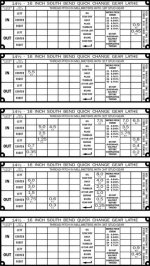
Fellow PM member nt1953 was kind enough to make me a set of alternate stud gears based on the math that he, kitno455, and others have discussed in other threads on this forum to make metric threads without a transposing set. These alternate stud gears have 31 teeth, 32 teeth, and 34 teeth respectively. With these three gears, plus the factory stud gear of either 18 or 36 teeth, the 16" single tumbler gearbox can make all standard metric fastener threads up through 8mm with less than 1% pitch error. It's not accurate enough for CNC leadscrews, but it's plenty good for any threaded fastener that's going to stretch when torqued anyway.

My 16" lathe came with the later 18-tooth stud gear from the factory. This yields a single tumbler gearbox range of 4-224 TPI. Older machines have a 36-tooth stud gear and a resulting gearbox range of 2-112 TPI. This doesn't matter directly for metric threading, it just means that two metric pitches (0.9mm and 0.45mm) can be generated with either factory stud gear, albeit in different slots on the gearbox. If that sounds confusing, it may make more sense when you see the screenshots below.

I see three potentially viable choices for the metric nameplate(s):

1 - Make a single plate that covers all possible metric pitch combinations. The plus side is only one plate is required. It could even be etched onto the reverse side of the inch plate I'm already making and just flipped when needed. The down side is it requires a lot of text in some slots due to overlapping pitches. One slot even has three combinations. I can etch it cleanly, but can I read it when I need to...?

2 - Make individual plates for each stud gear. Much easier to read, but then I have to figure out where to store several loose plates safely along with the loose gears when not in use.

3 - Make no [metal] plate at all and instead attach a paper version of the information, in a format that's easy on the eyes, to the inside of a wooden case for the loose gears. I really should make the wooden case regardless to store the gears, so the paper chart would be a no-brainer as a backup to a metal plate.

I'm looking for feedback on all three. What say you? If anyone has a good image of a factory 16" metric threading chart they can post, I'd love to see how SB did it with the transposing kit to take out all the pitch error.

Imperial Chart.jpg Metric Chart - All Stud Gears.jpg Metric Charts - All Stud Gear Combinations.jpg
 
I would print them on fridge magnet sheets, and swap them onto the gearbox as needed. Could store them stuck to the stud gear in a wooden box, or just slap them on the inside of the cabinet door.

allan
 
I would print them on fridge magnet sheets, and swap them onto the gearbox as needed. Could store them stuck to the stud gear in a wooden box, or just slap them on the inside of the cabinet door.

allan

That’s a super idea! I’m going to pass on making metal plates for now and put the time into a nice case with dry storage and a readable gearbox cheat sheet. I bet the fridge magnets would even stick on top of the Imperial brass plate.
 
"So I just noticed something I had missed before. On my 1943 single tumbler gearbox, the tumbler oil drip tube is positioned so that the tumbler must be all the way to the left (the 128 TPI slot) for the oil to drip into a depression on the tumbler casting.

Your plate above indicates the tumbler should be at the 192 TPI position, much farther to the right.

Is your oil tube located in a different spot? Or same spot but just bent to reach the 192 slot? "

Hello Tom,

I found the same issue on my 16" SB lathe. Before I received the NOS chart for the QCGB, I also positioned a new brass oiling tube, that worked, when the tumbler was all the way to the left, yet, the NOS chart indicated the 192 position, as yours does. I was tempted to redo the brass tube, to accommodate this position, but I didn't want to take everything back apart. This will be confusing and misleading to a future owner, so I might bite the bullet and redo it, before it goes out the door.

Brian
 
[Reposting -- previous image uploads weren't working correctly]

While working on the replacement threading plate artwork, I've also been experimenting with how to approach a metric threading plate (or plates) for the gearbox.

Fellow PM member nt1953 was kind enough to make me a set of alternate stud gears based on the math that he, kitno455, and others have discussed in other threads on this forum to make metric threads without a transposing set. These alternate stud gears have 31 teeth, 32 teeth, and 34 teeth respectively. With these three gears, plus the factory stud gear of either 18 or 36 teeth, the 16" single tumbler gearbox can make all standard metric fastener threads up through 8mm with less than 1% pitch error. It's not accurate enough for CNC leadscrews, but it's plenty good for any threaded fastener that's going to stretch when torqued anyway.

My 16" lathe came with the later 18-tooth stud gear from the factory. This yields a single tumbler gearbox range of 4-224 TPI. Older machines have a 36-tooth stud gear and a resulting gearbox range of 2-112 TPI. This doesn't matter directly for metric threading, it just means that two metric pitches (0.9mm and 0.45mm) can be generated with either factory stud gear, albeit in different slots on the gearbox. If that sounds confusing, it may make more sense when you see the screenshots below.

I see three potentially viable choices for the metric nameplate(s):

1 - Make a single plate that covers all possible metric pitch combinations. The plus side is only one plate is required. It could even be etched onto the reverse side of the inch plate I'm already making and just flipped when needed. The down side is it requires a lot of text in some slots due to overlapping pitches. One slot even has three combinations. I can etch it cleanly, but can I read it when I need to...?

2 - Make individual plates for each stud gear. Much easier to read, but then I have to figure out where to store several loose plates safely along with the loose gears when not in use.

3 - Make no [metal] plate at all and instead attach a paper version of the information, in a format that's easy on the eyes, to the inside of a wooden case for the loose gears. I really should make the wooden case regardless to store the gears, so the paper chart would be a no-brainer as a backup to a metal plate.

I'm looking for feedback on all three. What say you? If anyone has a good image of a factory 16" metric threading chart they can post, I'd love to see how SB did it with the transposing kit to take out all the pitch error.

View attachment 212561 View attachment 212562 View attachment 212563

I'd suggest that 1% isn't good enough to bother with special plates unless you only make coarse threaded bolts with short engagements. I use a 47/37 set of gears that's off by 0.021% and even that small error can start show up with very fine threads and long engagements. For most things it works great, but I'd be nervous if the error were any larger.
 
So I just noticed something I had missed before. On my 1943 single tumbler gearbox, the tumbler oil drip tube is positioned so that the tumbler must be all the way to the left (the 128 TPI slot) for the oil to drip into a depression on the tumbler casting.

Your plate above indicates the tumbler should be at the 192 TPI position, much farther to the right.

Is your oil tube located in a different spot? Or same spot but just bent to reach the 192 slot?

My tube is also pointing at number 128. I'm actually undecided what to do about it. Those particular tumblers are a bit notorious I suppose for the shaft and bore in the tumbler wearing, due in large part that the shaft is only supported on one side, so downward force as gear is working wears them quicker.

While I do think that, I also have an opinion that the wear is accelerated to lack of lube. Be it from guys not very intimate with the machine, missing the lube point, or oil running down tumbler instead of into felt. You pretty much have to get on your hands and knees to see if its getting lube. And I would guess in 70 plus years that didn't happen often.

I've painted all my lube points in yellow, in case I forget, including that one. Also whoever gets the machine when I'm dead might have a clue, lol. But I don't entirely trust the tube. Currently I get down and shoot oil directly to felt. I've toyed with the idea drilling and cross drilling shaft and put a grease fitting on it, but its another "to do" list decision thing, probably get around to it in 10 years, maybe.

I've been thinking to make a glass enclosed case, like a large picture frame to hang behind machine on wall. On it a pic of the machine with a description of what each lever and hand wheel does, lube points, etc. As well as keeping serial card, service/parts manual and such. I think it may even help me. If I don't run the machine often, I need to do a powered up dry run with cutting tools far from work to make sure I'm going the right way on each setting, lol.


Back
Top