What's new
What's new

Wiring drum switch to VFD?

Stronghold

Aluminum
Joined
Jan 5, 2015
Location
Jefferson City, MO
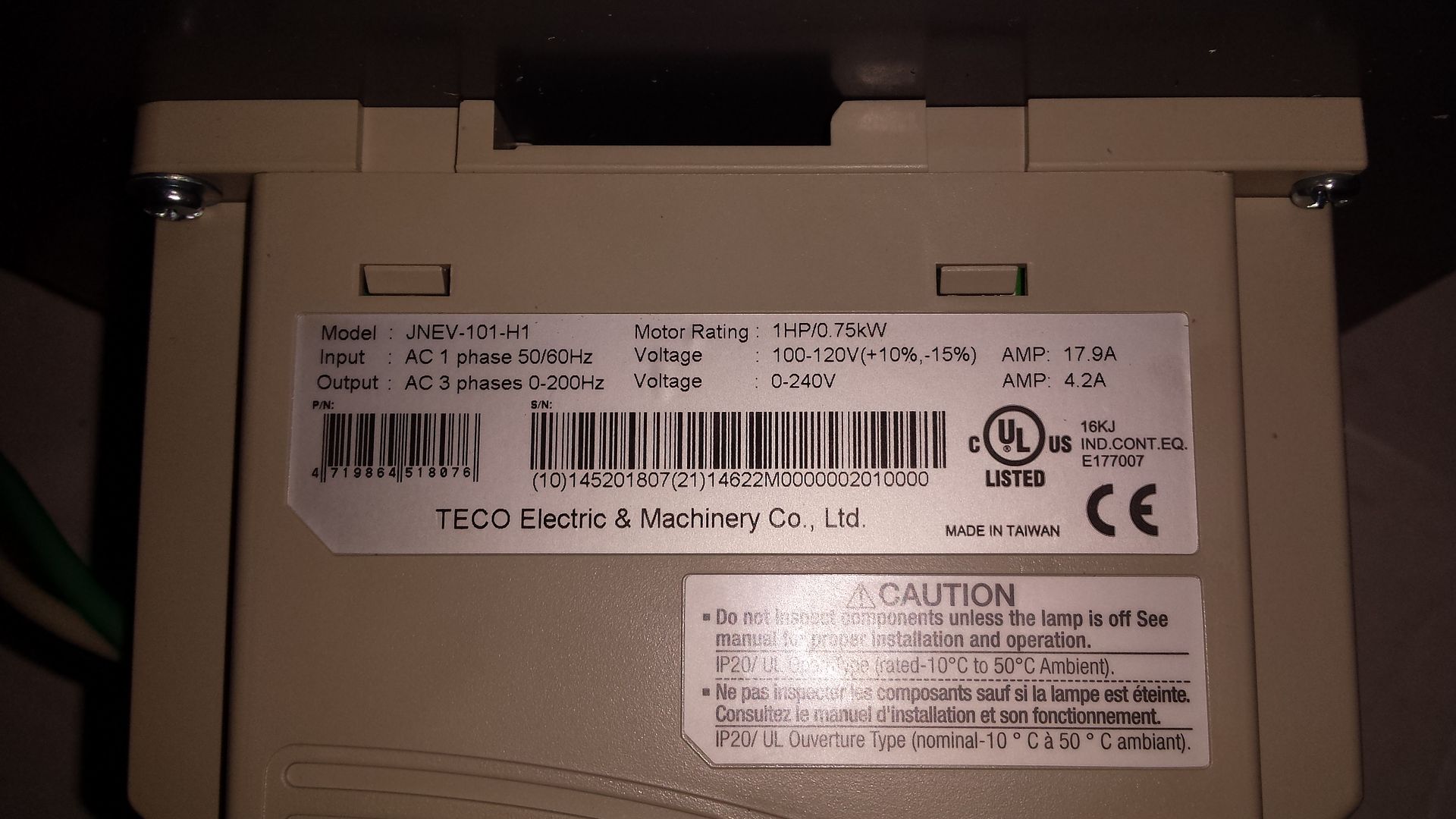
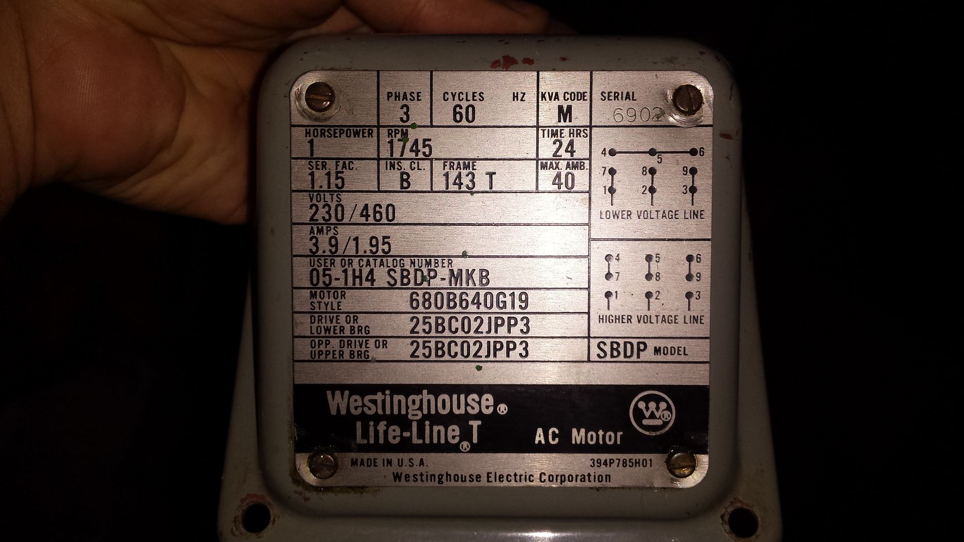
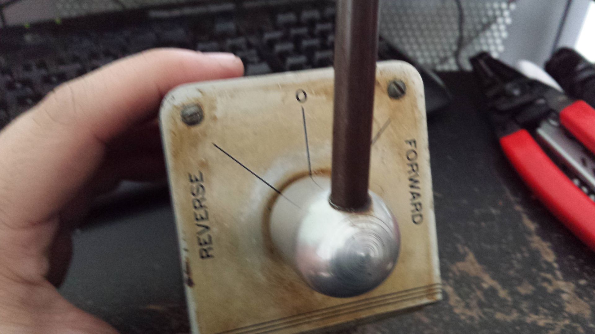
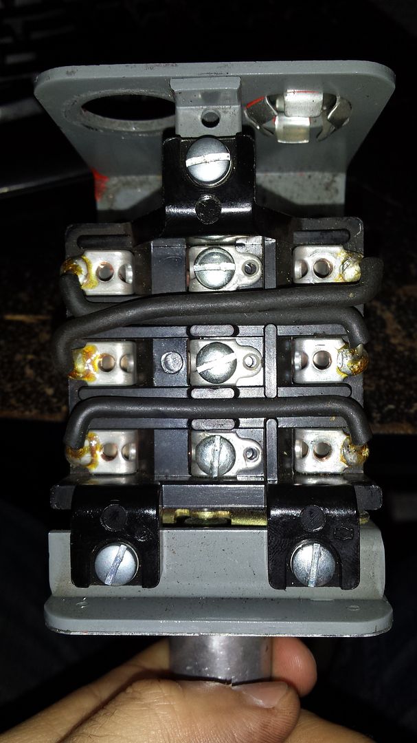
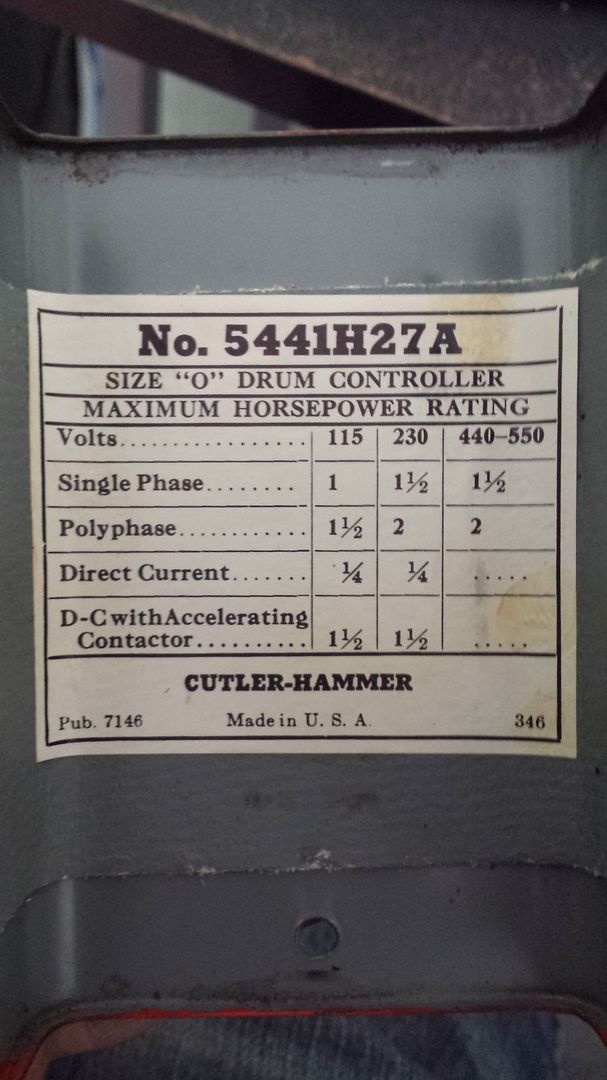
Hello again, gents. Now that I've got my lathe back up and running again it's time to move forward with the "to do" list. I have the original drum switch that is completely stripped of all wires except for the ones soldered to it. I want to use this to run my VFD and have zero clue where to start. I do know that I'm not supposed to put anything between the VFD and motor, and that in order to use the switch it will have to be hooked up to the VFD directly. As stated in another thread, I'm a complete noobie when it comes to electrical work. Does anyone have this same model and could show me their wiring setup when hooked to a VFD?

Thanks.

20150307_144357_zpsmjgsocc1.jpg

20150307_144410_zpsnvzwcmzo.jpg

20150307_144427_zps9rarc62k.jpg
 
You can wire that switch between the VFD and the motor. I have my mill that way for now. Not sure what it would hurt. You have to wait for the spindle to stop turning before you switch. What brand of VFD?
 
You can wire that switch between the VFD and the motor.
You can NEVER wire ANYTHING between a vfd and its load (motor).

That's called out in large letters in every vfd manual I've seen (many thereof).

All control switches are to be wired to the control terminal strip in the VFD.
There are usually several different configuration options, enabling you to use existing switches.

More specific advice will depend on the make and model of the vfd, and specifications for the motor being controlled.

- Leigh
 
VFD = Teco JNEV-101-H1
Motor = Westinghouse Life-Line T, 1hp, 3ph
OK. That's a decent combination.

Do you have the owner's manual for the drive?
If not you can download it here (PDF file): https://www.tecowestinghouse.com/Manuals/ev_operating_manual.pdf

All of your control lines connect to the green terminal block along the bottom front of the unit, shown on page 5.
On that same page you'll see the connections for your input AC power, at the top of the box, and lines to the motor at the bottom.

You'll find a detailed description of all the connections to that green terminal block on page 9 of the manual.
The input and output power connections are shown on page 10.

We need a bunch more info to proceed.
What is your AC mains power, 120 volts or 240 volts?
What functions do you want? A simple FWD / OFF / REV using your drumswitch or something more complicated?

- Leigh
 
You can NEVER wire ANYTHING between a vfd and its load (motor).

That's called out in large letters in every vfd manual I've seen (many thereof).

All control switches are to be wired to the control terminal strip in the VFD.
There are usually several different configuration options, enabling you to use existing switches.

More specific advice will depend on the make and model of the vfd, and specifications for the motor being controlled.

- Leigh

My Danfoss 5000 series VFT, which provides 3 phase to my whole workshop, states in the technical data (amongst a lot of other useful data):-

Switching on output Unlimited
protected against short circuits on motor terminals
protected against earth faults on motor terminals

They're expensive (new), but they're quality.
 
If you are putting a VFD on the motor then toss the drum switch. Put a small
box in its place with a 5K variable resistor, and SPDT center off toggle switch.

This gives you everything you need.

If you feel strongly about using the drum switch then put it back on but you'll
still need a box for the variable resistor.
 
Using the drum switch will get you up and running the quickest, although it's not usually the way it's done. I've marked up the picture of your drum switch and attached it. The numbers that I've scrawled in on the terminals refer to the green terminal block on the VFD. There are also two very small dip switches, both need to be in the "up" position.

Set your parameters as follows:
F04=001
F05=001
F06=000

You'll need to set F07, F08, F01, F02 to your liking. If Rev and Fwd are backwards, you can either physically interchange wires 4 and 5 in the drum switch, or do it in software using parameters F11 and F12.

You'll still need a method to switch power to the input of your VFD. If you're going with 115V input, you might get away with a single pole switch, in conjunction with a receptacle. I do it that way, and while the switch is not motor rated, it only serves to power up the VFD. And my breaker panel is less than 20 feet away, as well. I do my speed control using the knob on the VFD, with the VFD mounted out of the way in the well under my chip pan. I just reach down and don't find it very inconvenient.

drum switch.jpg

Paul
 
The numbers that I've scrawled in on the terminals refer to the green terminal block on the VFD.
Paul,

I don't see any annotations on that photo. It looks exactly like the one the OP posted.

You'll still need a method to switch power to the input of your VFD.
If you're going with 115V input, you might get away with a single pole switch, in conjunction with a receptacle.
This thing draws 18 amps @ 120v input. That's right at the upper limit of a 20-amp switch and outlet.

I would suggest using a proper fused disconnect. A twist-lock plug could be used if disconnection is desired.

- Leigh
 
Didn't realize he's got 18 amps - I'm on a 15 amp ckt.
Yep. 17.9A, visible in the photo of the VFD label.

That's really too high even for a 20-amp circuit, since you're not supposed to load any circuit more than 80% of capacity.

That would argue for a 25-amp fused disconnect or breaker box, with an appropriately-sized twist-lock plug/socket.

- Leigh
 
Guys it's a one hp motor, it only draws 4 amps, three phase.

This translates into at most 8 amps single phase including generous
conversion loss. No way the rig is going to draw 18 amps, that's
the number on the over-sized VFD. If the motor parameters are set
right, it can be plugged into a 15 amp branch circuit.
 
Hmm, closer inspections show it IS a 1 hp drive. Why the huge conversion loss in this
thing?

1 hp = 750 watts.

call it 1000 watts for motor eff of .75,

1000 watts at 120 volts is 12 amps.

12/18 is about 60 percent eff for the VFD. Seems low to me.

If the motor's not being run at full hp rating it might well work on a 20 amp branch
ckt. (and while a twist-lock cordset is nice, a regular flat-blade plug will still
serve as a disconnect)
 
Wire vfd direct to motor and use drum switch to control vfd.

Search sb area for my thread on doing this with same switch.

You need to rewire the jumpers and bend the contactors.

In short you have 3 stacked switches that are on-off-on

Top one is wired for start or run both ways.

Middle is wired in stop both ways and needs to make first.
Last is wired for reverse in one side.

Locate the connections for those logic inputs and wire to switch.

Confirm if vfd can be tested without motor and test operation without motor until you get it right.
 
Guys it's a one hp motor, it only draws 4 amps, three phase.
Jim,

We're talking about the 120-volt primary side. It draws 17.9A max.
That's shown in the photo of the VFD nameplate above.

The motor being used is a full 1 hp, so it's a max load condition.

Given that you're not supposed to load a circuit more than 80% of its nominal rating, you need a 25-amp plug/socket to meet code.

Of course, they don't make 25-amp twist-locks, so you have to go up to 30 amps.

You could fudge it and use 20-amp twist-lock connectors. That's probably what I would do.

Depending on where you buy them, a male/female pair would run $50 - $60.

Note that I'm talking about industrial-grade NEMA-type connectors, not DIY homeowner stuff and duplex wall outlets.

- Leigh
 
Not disagreeing on the nameplate on the drive.

What troubles me is that working the numbers the drive
should draw less than that. I'm trying to figure out where
the ineffeciency is in the system.

I doubt he's running the thing full 1 hp on a heavy ten. He could
reduce the motor size parameter on the drive to keep from having to
run a larger service to the lathe. A 10L works just fine on 3/4 hp.

In fact with the original leather belt, that's about all it could use.
 
What troubles me is that working the numbers the drive should draw less than that. I'm trying to figure out where the ineffeciency is in the system.

I doubt he's running the thing full 1 hp on a heavy ten. He could reduce the motor size parameter on the drive to keep from having to run a larger service to the lathe.
A 10L works just fine on 3/4 hp.
Hi Jim,

I agree. The efficiency is pretty bad, but not that much worse than other 120v/1ϕ-input VFDs from the various manuals I have here as PDFs.

The low probability of full-power operation is the reason I suggested using 20-amp industrial connectors.

- Leigh
 
I have my 10L with a 1 Hp motor running of a 15A 110V outlet with a Vacon inverter. Works mint!

I think that the part you missing is that the output power is 240x4.2xSQRT(3) =1746 W (SQRT(3) is for three phase power.

input has to match output power at 100V also so 100x17.9 = 1790W


Ulf


Back
Top