What's new
What's new

Wiring up a GE KC series motor

jackk669

Plastic
Joined
May 3, 2018
I have a South Bend Lathe with what appears to be a fairly common KC series 1/2HP motor. The wiring was cut when it was moved, several years back, and now I'm trying to get it connected back up.

I've dug through some posts here, as well as googling and watching a number of youtube videos, the most useful of which was this one (see diagram at 11:58): a subscriber asked how to wire a harbor freight motor with a reversing switch - YouTube

In looking at my motor I see the following specifications:
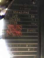
Machininst IMG_3555.jpg

According to the diagram in that youtube video, the connections seem to be configured for CCW rotation as we have the left hand L (equates to 1?) jumpered to connections 2 and 3, with the other L (6?) jumpered to 4 and 5.
Machininst IMG_3556.jpg

In extrapolating a little further, his diagram would imply that we need to connect the Live or Hot to 4-5-L and that the Neutral should be connected to one of the two extraneous wires which don't go to that landing board - one of which is blue, the other of which is red.

Most of the information I have found on the web, for this series of motor, uses standard colors, so I'm hoping that these two red and blue wires are standard. I do have the reversing connection board, but don't care about connecting it up as I only want the thing to run in one direction.

Do my assumptions sound likely, or have I misconstrued something?

Am I likely to damage anything if I connect it up wrongly?

Any other helpful information would be greatly appreciated. Thanks!
 
Last edited:
L stands for “line”, and would represent terminals 1 and 6. This is what you connect your hot and neutral to from your feed. Terminals 2 & 4 and 3 & 5 represent your run windings. When 2 & 3 and 4 & 5 are jumpered, this means your run windings are connected in parallel and the motor is set up for low voltage. If both jumpers were removed and installed between 3 & 4, the windings would be in series and the motor would then be set up for high voltage. Direction is determined by the flow of current through the starting windings and capacitor. My guess is that is what the blue and red leads are. One lead should be connected to neutral, and the other to your hot lead. Switch them to reverse direction. I like to verify connections using a multimeter first. You can check the red/blue leads by testing the resistance across them. If they are the starting windings (and capacitor), resistance will start lower and increase to infinite when you test it. Then reverse the leads, and it should do the same.

Edit: spelling errors


Sent from my iPhone using Tapatalk
 
Here’s my guess of how your motor is wired.

Notice the two spade connections, one on the jumper and one connected to terminal 5. My guess is that it’s designed for the capacitor leads to connect here. Then you just switch the leads to switch rotation. The connection on the jumper ensures the start windings only see 120V if the motor is wired for 220V. This also means that the jumper with the connection should always be installed between 2 & 3 when set up for low voltage.

-Keith

2a7ee65eff5237602db5aed027035446.jpg


Sent from my iPhone using Tapatalk[/QUOTE]


Sent from my iPhone using Tapatalk
 
L stands for “line”, and would represent terminals 1 and 6. This is what you connect your hot and neutral to from your feed. Terminals 2 & 4 and 3 & 5 represent your run windings. When 2 & 3 and 4 & 5 are jumpered, this means your run windings are connected in parallel and the motor is set up for low voltage. If both jumpers were removed and installed between 3 & 4, the windings would be in series and the motor would then be set up for high voltage.

Okay, this makes sense, and matches up with how I believe things were setup.

Direction is determined by the flow of current through the starting windings and capacitor. My guess is that is what the blue and red leads are. One lead should be connected to neutral, and the other to your hot lead. Switch them to reverse direction.

That should mean that the motor will start up no matter which way around the hot and neutral are connected? I have tried

I like to verify connections using a multimeter first. You can check the red/blue leads by testing the resistance across them. If they are the starting windings (and capacitor), resistance will start lower and increase to infinite when you test it. Then reverse the leads, and it should do the same.

This is great advice - I don't have the technical knowledge to know how to troubleshoot this kind of thing - thank you!
 
Here’s my guess of how your motor is wired.

Notice the two spade connections, one on the jumper and one connected to terminal 5. My guess is that it’s designed for the capacitor leads to connect here. Then you just switch the leads to switch rotation. The connection on the jumper ensures the start windings only see 120V if the motor is wired for 220V. This also means that the jumper with the connection should always be installed between 2 & 3 when set up for low voltage.

-Keith

Thanks Keith for taking the time to look into this. I'm not sure I entirely follow your second post. It seems that you are saying that the motor does not have the starter capacitor inside? If so, this would explain why I can't get it to start. Do you have an idea of what the capacitor setup should look like if it's not inside?

One thing which might not be clear from the bad cellphone photo, is that the dark grey blob of grey cloth tape seen in the lower right center of the picture is not attached to the jumper board. The bundle of cloth tape is a join between the grey wire disappearing out of the bottom of the photo and the red wire that appears from the below the jumper board where the number 3 is printed. There is currently nothing connected to the top of the jumper board. There may be connections on the underside, but I'm not currently ready to dismantle the motor and see how things are connected up below. There *was* a jumper wire under the L screw terminal of the L-2-3 jumpered connections.

I will meter the stuff you mentioned above and report back. Thanks!
 
Okay, so I've had a multimeter across the red and blue wires, and one direction gives 340 ohms, the other gives 430 ohms, not noticeable increase in resistance, so it would appear that there is no starting capacitor across these wires?

I am going to have to look at the reversing box which was attached to the jumper board as the starting circuitry is probably inside.


Back
Top