What's new
What's new

Did I mess up buying this?

Andrew937

Aluminum
Joined
Mar 20, 2009
Location
Dayton Ohio
I have an old round ram J head Bridgeport and a Southbend heavy 10 that need power. I plan on acquiring a large DoAll bandsaw and a 3 phase pedestal grinder at a later time.

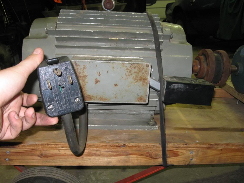
I found a 20hp RPC for cheap and bought it. I know it's probably too big but I drove out to see it and had the money in my pocket. This thing is huge! Upon getting it home and plugging it in I got kinda scared. This thing is loud and intimidating. Seems to spin a little fast.

Guy said that his late father built it and ran large welders off it.

Could you guys check it out and tell me what you think?

IMG_1176.jpg


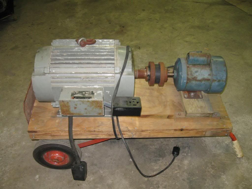
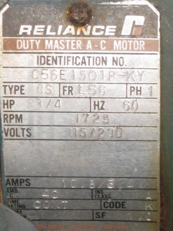
Small motor with a 110 plug
IMG_1175.jpg


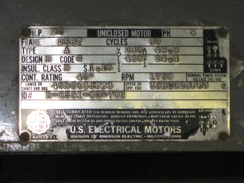
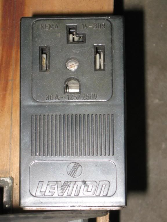
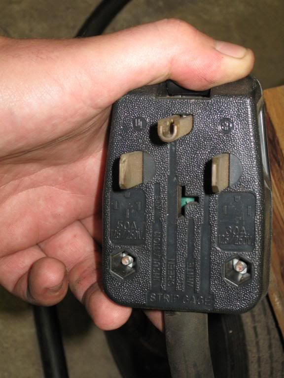
Large motor with a plug bigger than my 220 Linclon 175sp welder plug and a very large outlet.
IMG_1177.jpg
 
After reading a ton on phase converters, I'm not even sure that's what this is. Here is a video of me pluging in the 100 motor. Pardon the swearing.:D
 
The little motor is only there to start the big motor.

Unplug the little motor after you plug in the big one
or there may be smoke from the little one after a while.

This looks like a fairly standard rotary converter setup.

Jim
 
Unfortunately, your driving motor is only 3/4HP. This means that you will never generate more than 3/4HP on the big motor.
The small motor is a "pony" motor that does nothing but get the big motor up to speed. Most builders use some type of contact wheel that allows the pony to disengage, but it should work OK as it is.

The sequence of operation is:

Apply power to the pony until the motors come up to full rpm.

Kill the power to the pony.

Throw the switch that connects the 20 hp motor to your panel or machine.

Run your machine, knowing that you will not outgrow this RPC anytime soon :D

-------------
Barry Milton
 
Fellas, I don't think that there is any conection between the two motors other then the shaft. On the large motor, we've got a very large 4 prong plug and a receptical of the same pattern.

How could my standard 220 1 phase be turned into 3 phase with just one large motor?

Is the box on the 20hp motor the "static" 3rd leg?

I will go take some more pictures of the plugs, box and connections.
 
By the interaction of the rotating magnetic field formed by the single phase on the windings. What it looks like is the line cord on the large motor has a standard three prong plug as is used for 240V single phase, such as is often used as a receptacle for electric ovens or clothes dryers. It has prongs for both sides of the 240V circuit and a safety ground.

The outlet on the box looks like one of the standard sizes of receptacle used for four prong pugs; one for each line of the three phase circuit and the safety ground.

As others have said, the large motor needs to be spun up to speed before power is applied. Once running at speed it acts as a rotary transformer and generates voltage on the third leg. Meanwhile, the pony motor should be disconnected and just goes along for the ride.

One thing you need to do is to identify which is the "manufactured leg" coming out of the motor being used for the converter. Two legs wire to the receptacle, motor, and line cord, while the third is connected only between the motor and receptacle. The voltage on this third leg won't be very stable, and if the machine has any single phase loads (lights, control transformers for push button control stations, they should be wired between the two legs connected to the single phase line.

The three phase motors, however, will be happy with all three.

Dennis
 
Did anyone watch the video? Is the thing supposed to be that loud?

Here are the pics of the large plugs and receptical coming from the box on the large motor.
IMG_1184.jpg

IMG_1185.jpg

IMG_1186.jpg
 
I have a store-bought 5 hp RPC from the company in Arizona that works very well for my 3hp, 3 ph Webb Mill. It's a little noisy when started but when the Mill is turned on it quiets down nicely. It starts automatically with a relay.

The RPC shown here looks pretty good to me. I'd probably change it so that the Pony motor would start the big motor with a V-belt and a hinge to remove it from action once the big motor started.

Here's mine.

GeneralPhotos003.jpg
 
After reading a ton on phase converters, I'm not even sure that's what this is. Here is a video of me pluging in the 100 motor. Pardon the swearing.:D

Sounds like bearing noise to me, that's easy to fix. Just take it apart and replace the bearings. Could be some misalignment in that coupler setup too.
 
Can you remove the coupler and turn the big motor shaft by hand. Do you
feel any slight resistance. This is by no means a go/nogo test. Should be
smooth though. Bearings for electrical motor fit do not cost much. Probably
$20-$40 for that beast. I use SKF brand. If the end cups enclose the bearings
then shielded ones are good enough. Otherwise get ones with rubber seals.
While you are at it you can clean out any dirt on the rotor and stator. And then
paint the whole thing. I think you may have oversized your needs but if you
like it then use it. Use it for a while and monitor your electric bill. You may be
disappointed but I hope not.
 
Hi Jim, Thanks for visiting my thread. I saw you posted in a lot of other phase converter threads and your apparently the man in that area of expertise.

No I didn't plug in the 20hp 3Phase motor because my welder plug I thought might fit did not fit. I only plugged in the 110 motor for a second to see if it would work. As you can see it does and takes a long time to slow and stop after it's unplugged.

What do you think of this contraption? Is it even a phase converter?

What would be my next step?

I've got an electrician friend of my dads coming over in a couple days who worked at GM powering up the big machines in the plant but we'll see if he knows about home shops and phase converters.
 
Jim's ons the right track here
your not running it right
you have to also apply 220 power to large motor
i would guess the routine is to plug in the little motor
then unplug it and then get the big motor plugged in before it stops turning

yes its a phase converter
but a bit off the beaten path for design
 
Precisionworks gave a pretty good rundown on operation, in his post above.

Although, I would probably energize the idler motor (big one) before taking
the power off the pony motor (small one).

Things to think about:

1) you need to fuse the incoming power for the idler for the conductors
you are using. The inrush current for the idler will be pretty low so
that is not a concern. But you do need to size the overcurrent protection
(fuses) upstream of the converter based on the smallest wire size you
are running from it.

2) as others have rightly suggested, check the bearings on all the motors
by uncoupling them and finding out where the noise is coming from. Replace
those that are worn. If you are lucky it will be the small motor.

3) when folks say 'unconventional' this is because of the direct coupling
between the small motor and the large one. It makes for a very compact
unit but then the pony motor is spinning all the time. Lots of folks like to
uncouple the pony motor but the configuration on this idler is OK and the
direct coupling is not a show-stopper.

Read the sections at the top of this forum, there's a lot of information there.

Jim
 
That's a fine example

That's a fine example of a very simple rotary phase converter, Henry. This segment of the forum is about things like rotary converters.

The big plug you have... with just three prongs... that's 240v single-phase coming in. Two hot leads and one neutral. That provides power to spin the big motor (aka 'idler'), and also carries current that eventually powers your mill.

The outlet on the unit... has four prongs. There's a ground wire, and three hot wires. These three hot wires coincide with the three hot wires that power your mill.

The little motor is the 'pony' or starting motor. Plug this rascal in, and it gets the bigger idler motor spinning. Once up to a reasonable speed, the idler (a big three-phase motor) will actually run on single-phase power... and in doing so, it'll generate a rough facimile of a third phase... well enough to run your mill.

As big as this beastie is, you'll be hard pressed to find a garage tool that it won't run.

While a disconnection method has been suggested, there's really no necessity to unhook the pony from the idler... just shut off it's power and let it spin... all it's doing is adding a little intertia, which isn't a problem. The only advantages to going to a belt-drive are 1) allowing 'clutch slip' during startup, 2) allowing a reduction ratio and 3) reducing vibration due to slight malignment or shaft/coupler runout.

Yep, it's noisy- probably sat for a while before you came to obtain it... clean up/change the bearings and move it from a plywood board to a pair of steel runners on rubber feet, it'll cut down the 'speaker effect'.

While you're at it, if you have access to some contactors and capacitors, and a timer relay, you could eliminate the need for dancing-with-plugs... just give it an on-off control, and a little run capacitance for balancing the generated leg a little...
 
What Dave K said, except for one thing: the incoming
connection to the large idler motor, is two hots and
*ground* connection, not a neutral. This setup does not
require a neutral to work (aside of course, the smaller
motor which is run off 120) but it *does* require a
green wire personal protection ground which is what the
third contact on that plug is for.

Jim
 
If I am reading the amp rating of the plug correctly, it is a 30 amp setup. With 30 amps single phase coming in you will have 5 hp maybe 6 hp RPC. A 20 hp rpc will require a 100 amp minimum service. I would recommend upgrading this to use disconnect switches to turn the power on to the motor and you can increase the circuit size to 60 amps at this time and you will have a very solid 10 to 12 hp RPC. There is no use going above this amperage unless you want to upgrade the RPC by adding run capacitors because a idler without run caps should be twice the size of the RPC rating.
 
Andrew, all above is good stuff but it may come off as more complex than it really is.

Here is a sketch I drew as a guide to build my RPC.

I had a 100A disconnect on hand, so I used it. It's just a big 3Ph switch. You need something that will function the same, IE, kill the feed. The plug is not good enough. It's not a legal disconnect and the arcing will erode the prongs and could create dampness in your pants.
FrictiondriveponystartRPCIII.jpg

You can see the 2 hot legs of single phase 240V, plus the service ground coming in the top.

Those two legs continue on down to two of the 3 wiring groups in your idler, where, if the idler is spinning 1725, it will run, pony no longer needed.

Not only will it run but the third, "Spare" group of wires in the box on your idler, will provide the final leg of 3Ph power. The color is meant to be orange, (B) convention for "the manufactured" leg. It really is that easy.

Reading your initial post, I got the idea that you are confusing an RPC with a motor/generator set. It is not. Were it, the driving motor would be "bigger" than the generator and stay on. Instead, you will be using the 2 hot legs you already have, the idler generating the third internally.

Follow the wiring diagram above and it will work. I'm making the assumption that there are no mysteries on how to start the 120V pony, though it should also have a switch.

Just in case, while you are in the idler junction box, check to make sure that the internal wiring of the idler motor, follows the "LO-VOLTAGE" diagram in the lower right hand corner of the idlers spec plate. "Hi-voltage" is for 480V, you can't get there from here.:)

I have little doubt that it's wired that way already, minus the disconnect, with the downstream 3phase and ground available at the 4 hole receptacle.

Bob


Back
Top