What's new
What's new

Pic's of my first VFD install !!!

383FormulaS

Plastic
Joined
Oct 2, 2011
Location
Panhandle of Texas
Just have a few finishing touches, but everything went very well. Better then expected I should say, and much to my surprise very low on the frustration scale:angry:. Thanks to all here on the forum that helped me out and the guys at Wolf Automation this was a very pleasant experience and I couldn't be happier with the out come.:D

OH Yeah its only on the cart temporarily still working on the room it goes in.

Mill-1.jpg

Mill5.jpg

Mill2.jpg

Mill3.jpg
 
Nice job on the install. The only issue I see, in my opinion, is the controls would be more ergonomic if on the left side. Usually my right hand is busy with the quill handle, the left with the controls, such as in power tapping.
 
Nice job if your are left handed.. :)

There is a mill somewhere under all that DRO and powerfeed wiring right????

Miles of loose wire to snag, get cut, and nicked/coated by chips....
 
If the OP is a firm believer in gradual improvement (you know, that Kaizen stuff), then I will gently mention how I install the water-tight class of flexible conduit. I prefer the fully plastic, no metal style.

I use the Cantex brand of PVC conduit connectors (Home Depot, I recall) Cantex has the wrench flats molded onto the terminal connectors.

Modified water-tight flex PVC connections 001.jpg
Terminal connector on the top, female adapter in the middle, flex conduit on the bottom.


Modified water-tight flex PVC connections 003.jpg
I cut the socket from the terminal connector.

Modified water-tight flex PVC connections 004.jpg
The modified terminal connector is installed in the enclosure, threads facing out.
The female adapter is glued to the flex conduit.

I prefer this method for a few reasons:

I usually have the fittings on hand.
You can slip a box-end or socket wrench on those flats.
The glued fitting cannot work loose as the threaded fittings can.
 
Steve,

Because you prefer a different style of flex surely doesn't mean that to use such an item would automatically be a 'improvement'! :rolleyes5:

The flex the OP used is metallic sealtite...it has conductive construction that bonds all boxes and enclosures together for safety and grounding. The professional electricians that use this item won't be found in the aisles of Home Depot...mingling with the DIY'ers such as yourself.


383FormulaS,

Great looking work!:)


Stuart
 
I have seen enough industrial equipment with the flex conduit pulled out of the connector to tolerate the need to either run a green wire inside the flex, or to ensure equipment bonding some other way.

I do appreciate your observation, I appreciate it.

And now I put you back on Ignore.

I did a little research regarding Atomarc's observation, and this is what I found:

From Article 250.118 Equipment Grounding:

70-110R NATIONAL ELECTRICAL CODE 2005 Edition
ARTICLE 250 – GROUNDING AND BONDING
250.118 Types of Equipment Grounding
Conductors. The equipment grounding conductor
run with or enclosing the circuit conductors shall be
one or more or a combination of the following:
(1) A copper, aluminum, or copper-clad aluminum
conductor. This conductor shall be solid or
stranded; insulated, covered, or bare; and in
the form of a wire or a busbar of any shape.

(2) Rigid metal conduit.

(3) Intermediate metal conduit.

(4) Electrical metallic tubing with an additional
equipment grounding conductor.

(5) Listed flexible metal conduit with an
additional equipment grounding conductor,
and meeting all the following conditions:
a. The conduit is terminated in fittings listed
for grounding.
b. The combined length of flexible metal
conduit and liquidtight flexible metal
conduit in the same ground return path
does not exceed 1.8 m (6 ft) for feeders
and 15 m (50 ft) for branch circuits.
c. The additional equipment grounding
conductor is terminated at each
termination or junction point.


(6) Listed liquidtight flexible metal conduit
meeting all the following conditions:
a. The conduit is terminated in fittings listed
for grounding.
b. For metric designators 12 through 16
(trade sizes 3/8 through 1/2), the circuit
conductors contained in the conduit are
protected by overcurrent devices rated at
20 amperes or less.
c. For metric designators 21 through 35
(trade sizes 3/4 through 11/4), the circuit
conductors contained in the conduit are
protected by overcurrent devices rated not
more than 60 amperes and there is no
flexible metal conduit, flexible metallic
tubing, or liquidtight flexible metal
conduit in trade sizes metric designators
12 through 16 (trade sizes 3/8 through
1/2) in the grounding path.
d. The combined length of flexible metal
conduit and flexible metallic tubing and
liquidtight flexible metal conduit in the
same ground return path does not exceed
1.8 m (6 ft).

e. Where used to connect equipment where
flexibility is necessary after installation,
an equipment grounding conductor shall
be installed.


(7) Listed liquidtight flexible metal conduit with
an additional equipment grounding conductor
and meeting all of the following conditions:
a. The conduit is terminated in fitting listed
for grounding.
b. The combined length of liquidtight
flexible metal conduit and flexible metal
conduit in the same ground return path
does not exceed 15 m (50 ft) for branch
circuits and 1.8 m (6 ft) for feeders.
c. The additional equipment grounding
conductor is terminated at each
termination or junction point.
(8) Flexible metallic tubing where the tubing is
terminated in fittings listed for grounding and
meeting the following conditions:
a. The circuit conductors contained in the
tubing are protected by overcurrent
devices rated at 20 amperes or less.
b. The combined length of flexible metal
conduit and flexible metallic tubing and
liquidtight flexible metal conduit in the
same ground return path does not exceed
1.8 m (6 ft).
(9) Armor of Type AC cable with an additional
equipment grounding conductor and as
provided in 320.108.
(10) The copper sheath of mineral-insulated, metalsheathed
cable.
(11) Type MC cable where listed and identified for
grounding in accordance with the following:
a. The combined metallic sheath and
grounding conductor of interlocked metal
tape–type MC cable
c. The metallic sheath or the combined
metallic sheath and grounding conductors
of the smooth or corrugated tube type MC
cable.
(12) Cable trays as permitted in 392.3(C) and
392.7.
(13) Cablebus framework as permitted in 370.3.
(14) Other listed electrically continuous metal
raceways and listed auxiliary gutters.
(15) Surface metal raceways listed for grounding.

While many experts and Authorities Having Jurisdiction are perfect and complete in their comprehension of the previous section, it seems much easier to install a ground wire in any run of liquid-tight flexible conduit.

Cause life's too short for pissing contests that can be negated by a few feet of green wire.
 
Nice job if your are left handed.. :)

There is a mill somewhere under all that DRO and powerfeed wiring right????

Miles of loose wire to snag, get cut, and nicked/coated by chips....

Like I said I still have some finishing touches to do, the wiring your seeing I plan on tiding up. The dro wiring is braided protective cable and as far as the power feed wires I don't see anyway around them from how they are plus they have been on this mill since 2000 and show no damage so I'm not to concerned. I can see what people are saying on my control location not being on the left and I gather I must have botched this on up but I have read no where of anyone giving advice on it needing to be on the left side. I mainly tried to go off some pics of other newer mills with vfd set-ups and most if not all of them show to be on the right and not the left so that's where I came up with the location. I could always move the 3pos. switch up to the mill head and leave the rest alone. Newbie mistake but I see the point.
 
Looks good. But I would not have mounted the start/stop buttons on top because of metal chips
landing there. You can put a clear plastic overlay there held down with small magnets, If the overlay
gets burnt by some chips it can be easily replaced. I would have provided a display for speed.
 
Guess you will BOTH throw brickbats if I mention running the low-voltage (Class 2?) control wires inside stainless-braid-covered dishwasher or washing machine supply hook-up tubing, then. So I'll just not tell anyone about glomming some of it whilst 'sale priced'...

Bill

Bill,

How curious...when you post, Mr. Bausch donates a "like" and when Mr. Bausch posts, you donate a "like'! You two obviously think alike but does it go further than that? You fellows aren't Greek by any chance?:eek:

Stuart
 
Looks good. But I would not have mounted the start/stop buttons on top because of metal chips
landing there. You can put a clear plastic overlay there held down with small magnets, If the overlay
gets burnt by some chips it can be easily replaced. I would have provided a display for speed.
I have came across some other buttons that have rubber covers after I already wired these in plus they are just the on off to the vfd not start stop.( I also try to vacuum chips up after each use) Most everything that I used was stuff I already had or came off used equipment. I have thought about speed display in RPM but others on here said it wasnt needed, I have a good idea what speed the mill is running at with the setup now. I programed the vfd to coincide with the numbers on the speed dial 3=30Hz 6=60Hz and so-on, I will still make belt changes but will fine tune with the speed control. I'm still thinking about adding speed display in RPMs off the spindle but it will be down the road if I still think I need it. (Trying to do everything at once will make you go broke so a little at a time for me)
 
Good start!

Hi 383!

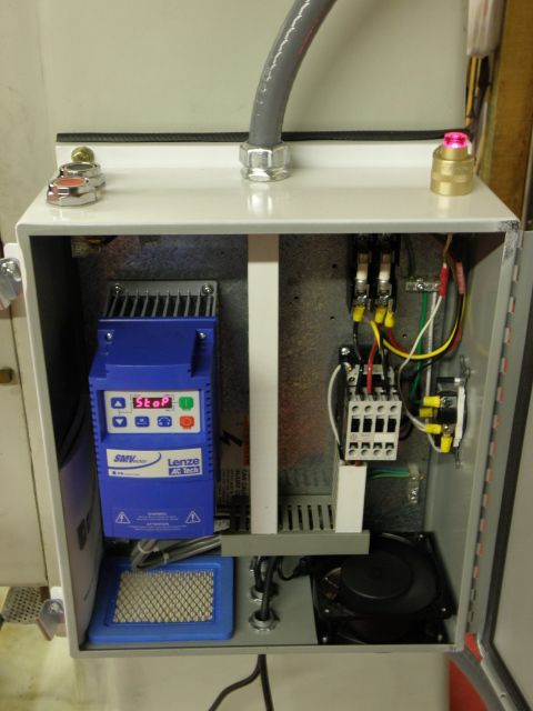
You've got a good start there, and I wouldn't be too worried about anything more than functionality on the first VFDification. The biggest challenge for most is actually getting it in a box, and hung on the side of the machine, wired up to controls, and then the guts to flip the switch and pray there's no flash-bang-smoke. After that, getting the parameter adjustments just-right. After using it a little, the position convenience will become apparent based on your machine's location, the type of work you're doing with it, and of course, your operating technique.

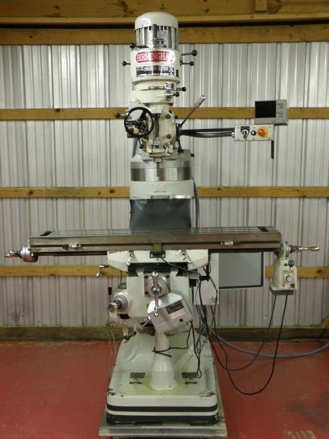
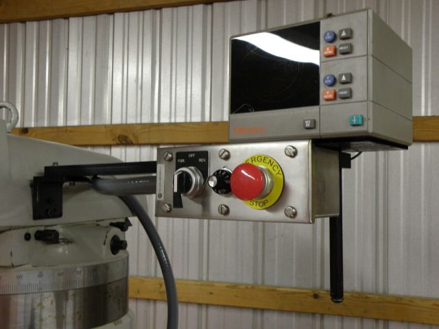
I can understand why you mounted the speed/direction/Estop where you did... it's very common to see machines with controls to the upper right... these controls are typically DROs (like yours) or a CNC control panel. For CNC machines, they have connection to the spindle direction/speed control, but the operator's usually not working handles, so it makes sense there. I'm sure that if you don't like it, you'll move it.

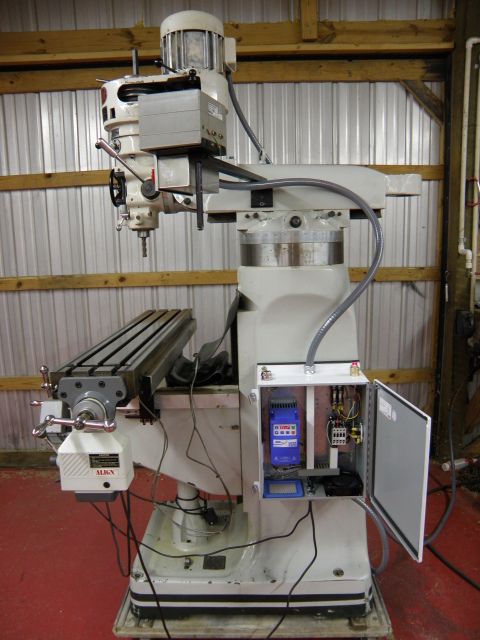
Like you, I mounted my VFD cabinet on the right side of the machine, and for two reasons- first being that there's a tooling locker on the left side of my BP's column... so the cabinet won't fit on the right, and the back of the machine isn't easily accessible for power switch operation, but the right side is easy to reach... and has a good mounting place.

As far as the wires, yeah, it can be difficult to wrestle those into submission. You've got quite a bit of moving real-estate there... that requires lots of wire, and big flexible tubing over it will not necessarily improve it's range-of-motion, aesthetics, or safety. I'm sure that, once in operating position, you'll have it tied off in positions that keep them out of harm's way. If you have to leave them free for motion on that LONG table, one thing you can do, is get some braided stainless shielding off of industrial signal wiring, and slip it over your wires... it fends off hot chips nicely... just hafta find a guy that works on stuff like that... or truck and railroad scales...
 
Not sure I totally understand your wiring, but the #1 rule of proper VFD installation is the use of shielded motor leads and separation from all other electrical circuits, especially low voltage (including 120 VAC) circuits. The most egregious violation is to use individual conductors in conduit with other wires in it. If you use shielded motor leads, you still want around 3 inches of minimum separation, but if unshielded you should have 12 inches of cable separation.

The stray currents from the drive (caused by common mode voltage) running around the mill can cause your DRO to go out to lunch and cause severe electrical interference with other electrical equipment in the shop. The shielded cable (properly bonded at both ends) is a low impedance return path for the stray currents to return from the motor to the drive. The shield must be properly bonded (connected) directly to the motor frame and drive backplane.

Most of the drive vendors that you guys are using do a tremendous disservice to the end user by not providing proper installation instructions. I cringe every time I see an improperly installed VFD............
Not to sure what your trying to understand about my wiring. The control cable is shielded going out the top and my shielded motor cable is going out the bottom. This was the best way for me to keep a good distance from the rest of the wiring. If you look at the pics closely you will also see that I have a common wire from the outlet and contactor coil wired to ground which is a major no! no! This was only temporary for testing and is now wired to a common where the mill sets in it permanent home. As far as how the shielded cable should be grounded it seems to depends on who you ask. Mine is grounded at one end whether that's right or not I'm not sure but that's a whole other can of worms that has been discussed endlessly on this forum, I rather this thread not start a pissing match on which ways right. The wiring in the pics has been cleaned up some-what and some changes have been made from the day I took these and so far no problems.


Back
Top