PWP
Hot Rolled
- Joined
- Apr 1, 2005
- Location
- Bourbon, Missouri
Follow along with the video below to see how to install our site as a web app on your home screen.
Note: This feature may not be available in some browsers.
Both Cap's are start. 125VAC and 413-500 mfd. 20 amps no load is seems pretty high. 22amps when both are connected together.

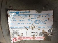
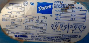
Bump. I'm hoping to get some answers for a very similar question. I have an American made (Wisconsin) "Doerr" brand 5hp / 29 amp rated single phase motor I'm cleaning up for an air compressor build. It has three large capacitors inside a metal box that is mounted directly on top of the motor. Two of the caps are the exact same, while one is different (but are all Dayton brand).
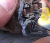
Unfortunately the labeling on the largest / different one is degraded to a point that I don't know what to look for to replace it.
They are;
Two black (round canister shape) Dayton brand - 1000-1200 MFD // 110/125 VAC // 1A571 // 235-8510-04 (they each have 2 poles + / -)
One silver (rectangular/or oval shaped) Dayton brand - 20 MFD // 370 VAC // 50-60Hz // 4X45QA or 4X450A or AX45QA or AX450A?? (has 2 pole sets for + / - / and gnd)
If you are certain those start capacitors are wired in series, then you can replace them with a 250-300uF 220v start capacitor.
Notice
This website or its third-party tools process personal data (e.g. browsing data or IP addresses) and use cookies or other identifiers, which are necessary for its functioning and required to achieve the purposes illustrated in the cookie policy. To learn more, please refer to the cookie policy. In case of sale of your personal information, you may opt out by sending us an email via our Contact Us page. To find out more about the categories of personal information collected and the purposes for which such information will be used, please refer to our privacy policy. You accept the use of cookies or other identifiers by closing or dismissing this notice, by scrolling this page, by clicking a link or button or by continuing to browse otherwise.