What's new
What's new

Amp draw

wildman9

Plastic
Joined
Dec 21, 2012
Location
Ontario, Canada
I have a Standard Modern 1340 with a 3hp 3 phase motor that says it is 3.5A. It has 1 leg that draws 20a when starting it in high gear. It is also very slow starting. I have a 5hp RPC and a 7.5 kwa transformer. When the motor is running it is drawing 3.5 a on the leg that draws the most starting and the other 2 are 1.5a. Would the problem be with the motor? I was starting to question the transformer, is 7.5 kwa enough for my application?

I should mention that it kicks the breaker in the starter if it runs very long in the higher gears. It has a breaker (reset) per leg and it is always the leg that has the high draw that trips.
 
Something certainly seems wrong there. While it's not totally out of the question for a 3HP motor to draw 20A on start up, it definitely is not right that your motor is drawing substantially more on one phase than the others. First, check that it's been wired properly at the motor junction box. This is probably a 220/440V motor, and if someone wired it improperly it could explain your issues. Ignoring ground, there will probably be three line wires and six motor internal wires, to be wired in one of two specific configurations involving three or four electrical connections. If you find it's been wired properly, then pull the motor and have it tested by a motor repair shop.

I don't know if Canadian electric code requires it, but you really should have that machine on a three-pole breaker so that all three poles are disconnected if any one trips. Separate breakers per leg may be how the starter was designed, but it's not a safe design.
 
it is a 575v motor and there are 5 wires in the junction box. There is no diagram though. The breakers are part of the starter, if it trips a breaker it automatically trips the stop switch or so it seems. At any rate the starter disengages.

So the motor may be wired wrong, not sure how I will figure that out, I may have to check with a motor re builder. All 5 wires are hooked up, 2 legs have three wires hooked together and 1 has 2, of course this includes the three wires from the drum switch.
 
The 7.5kva transformer is fine. Those lathes run very hot and it is under powered to run at high speed until well warmed up. Try measuring your voltage instead of trying to measure current draw.You might want to try it on a vfd, where are you in Ontario?
Rob
 
I read this differently....

most motors DO pull 600% rated current on startup.... 20 amps is 600% of 3.5 amps so THIS IS NORMAL.

You mention only high gear start; I assume from this comment it does not seem bad starting in the other gears? I also will assume then that THIS gear is the one that presents the largest load inertia to the motor, causing it the longest hardest startup acceleration. this too is normal and how stuff works.

now to running current of 1.5 vs 3.5.... this is likely telling you your phase-phase voltages out of rpc are not balanced: I would venture to say that since running no load should be around 1.5 amps on this motor, and you see that on 2 phases, then the 3.5a one is the MANUFACTURED phase from your rpc. I would continue and bet that if you measure the motor voltage phases while running with these currents you will find the 3.5a leg is significantly HIGHER voltage than the other 2; hence the higher current.

so I would say after gathering the voltage readings and proving it is an rpc issue, add the caps to rpc to fix it IF YOU WANT. since 3.5 is still below motor nameplate reading, maybe it is not an issue anyway - might be under load the voltage comes down and so motor is happy....

second, i would say dont start it in this gear and dont worry about it.
 
ok, so the deal with the extra wires in the motor, I wasn't thinkin real good last night, it has a brake on the end of the motor.

So the whole story goes like this, I first hooked the system up with a 15kva transformer, problem was it was a 208vac input, I was feeding it 240vac and therefor the output voltages from the transformer where in the 680vac range and the phantom phase was 708vac. The motor would start right away but it would dim the lights and carry on. So I picked up this 7.5 kva transformer, now the motor is hard and slow to start, no matter the gear, when comparing to the 15kva unit. The thing is this 7.5kva unit doesn't dim the lights and shows no indication of a large draw on the electrical source, the motor is just very slow to start and the rpc has quite a load on it. Plus the fact that it trips the breaker in the starter.

Now in the last post it was mentioned to add another set of capacitors to the manufactured phase to lower the amperage, will that not increase the voltage on that phase?
 
The 7.5kva transformer is fine. Those lathes run very hot and it is under powered to run at high speed until well warmed up. Try measuring your voltage instead of trying to measure current draw.You might want to try it on a vfd, where are you in Ontario?
Rob

I am in Forest
 
You will have to post voltages bearing in mind there are 3 phases and only one is real.I use this convention; lines 1&2 is utilite's, 2&3 start and run caps, 3&1 balancing caps. Tuning involves balancing the run caps on both the manufactured phases, remembering that adding caps to the 3&1 phase may counteract the starting caps effectiveness. If you ever get substantial voltage drop on the 1&2 phase, you must be seriously overloading something. I would want to disconnect the brake until problem is resolved.FWIW I have a similar sized dutch made lathe that previous owner replaced 3hp factory motor with 3hp single phase. It can take over an hour of running before it is hot enough to run highest speed.A thinner oil may help but will it protect the gears? I remember a Standard modern like yours that was too hot to keep your hand on at the end of shift, but still making perfect parts.
Rob
 
The voltages that are being presented right to the load motor, if you please.

Here's my guess on this: You'll find that that the voltages are balanced already
within ten percent line-to-line. Measure for the steady state running condtion.

Don't bother measuring any voltages, line to ground or line to neutral. Those don't
matter for your issue.

The next SWAG from this end of the world: your amp-clamp meter is doing a poor
job of measuring the currents flowing into the load motor. The larger currents
in the utility legs are mostly reactive. The smaller current on the manufactured
leg is mostly real.

This is how my 5 hp converter behaves. Voltages balanced within five percent.
Currents as measured by an amp-clamp (which gives the sum of real and
reactive currents) quite imbalanced. Load motors run fine.

In your case a totally uncompensated converter at 5 hp is a bit on the small
side for a hard-starting (gearhead lathe) 3 hp load motor.

If you get the steady state voltages close to in balance, it may start better.
Otherwise consider stepping up to a slightly larger idler motor for this machine.
 
ok, I let the lathe run in a medium gear, 700rpm I think it was, for about 1/2 hour. Then I measured the voltage. rpc out was 241, 249, 240 Transformer out was 627, 626 and 582.

I guess what I don't understand is why with the 15kva transformer did the motor start right up without laboring but dimed the lights and with the 7.5kva it labors to start but doesn't dim the lights? wierd if you ask me. Could it be that the 15kva transformer provided the current to start quickly and rpc worked harder to provide the input current where as the 7.5 is maxed out to provide the current to start the motor and rpc isn't maxed to provide the current that transformer draws?
 
The lights dimming mean voltage drop with the large transformer. The voltages listed are in the exact order I requested? (it is meaningless to list them willy-nilly) Are you certain there is not a choice of taps on the transformer? The ratio of input to output voltage should be same on all phases. Keep a written list of voltage under different loads at different places.If you interchange the inputs to the transformer does the incorrect ratio stay with the phase or the transformer? Your voltage is being boosted too much for a 550v motor, this can cause over current also, so you should try to borrow a transformer with taps. Most transformers I have seen have them.
Rob
 
They are not in any order, no. I don't know which is which to be honest. The transformer is a Marcus, you should be familiar with them. There are x0,x1,x2,x3 & h1,h2,h3. I have had no luck finding a 575vac transformer, other than the 15kva I have, but it is suppose to be 208vac input, I have 240vac. I am not real knowledgeable with this stuff and if I talk to 3 different electricians around here I end up with 15 different answers. I know if I paid someone to come in and set this up with the right stuff (so they think) it will be no different and I will be out thousands. Just as an example, I had an electrician tell me this transformer would work fine and would be well within the percentage tolerance for my motor and would not damage it. I don't know, it is very frustrating.
 
I guess what I don't understand is why with the 15kva transformer did the motor start right up without laboring but dimed the lights and with the 7.5kva it labors to start but doesn't dim the lights? wierd if you ask me. Could it be that the 15kva transformer provided the current to start quickly and rpc worked harder to provide the input current where as the 7.5 is maxed out to provide the current to start the motor and rpc isn't maxed to provide the current that transformer draws?

Listen to Rob & Jim - they both have good experience with rpc stuff.... I will give my swag on why above....

I doubt it is a CURRENT issue that caused the difference you saw: your 7.5kva xfmr is more than capable of providing way more current than that motor needs.

I think it is a VOLTAGE issue that can explain the difference. Two fold:

1) the 7.5kva xmfr, being SMALLER, will dip in voltage at the motor during this 600% start current draw, so it will actually be LOWER voltage than steady state.

2) your 15kva had WAY HI voltage to the motor.

Now look at how a motor works.... it wants a certain voltage to make the best torque possible. Torque is what turns the shaft, speeds it up against that high inertia load you have. Torque out of a motor across the line will go up or down by the SQUARE of the voltage applied.....

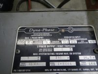
So in comes ur 7.5kva xmfr with 582-ish volts steady state - it probably dropped to 540 volts @ 600% start load!

Now the 15kva brute: not only did it NOT drop 40 volts since it was bigger, it also was wrong ration so you put 708-40 or 660volts into it!

It is a nominal 575v motor! so with 7.5kva xfmr, you under voltaged it by 575-540 about a 35volts! torque available to accel is less higher so it starts slower and pulls MORE current to make up for the lower torque it has available so lites dim.

It is a nominal 575v motor! so you over voltaged it by 660-576 about a 100volts! torque available to accel is HUGELY higher so it starts faster and does not require as much current to motor so lites dont dim.

I dont think diming lites is a good reason to go back to a radically wrong voltage on your motor to stop lites from diming (I know you didnt say you would) :) I propose that IF you let that motor run with those high voltages on it, being a 3hp motor with a thermal time constant of probabyl 30 minutes, it would have been too hot to put your hand on in 60 minutes and cooked itself in 90 - even no load.

You should consider buying a vfd and using it to give you the advantage of variable speed while reducing that 600% inrush current to 150% and making your lites happy.
 
don't get me wrong, I will take all the help I can get, I just need an education on how to tell what wire is what. I came looking for help because the local talent had me running in circles. I am very knowledgeable with 12vdc wiring diagrams and can fix any drivability problem on pretty much any car, so with some guidance I know I can figure this stuff out. I will go snap some pics of the schematic for the phase convertor and maybe we can go from there.

I am not really concerned with the dimming of the lights, it really was just an observation. The tig welder wound up to 200a welding aluminum causes more grief with the lights than anything else, er so I am told by the 1 in the house:willy_nilly:
 
here are some pics of what I am working with, I hope it helps.
 

Attachments

  • wiring 013.jpg
    wiring 013.jpg
    93.3 KB · Views: 274
  • wiring 006.jpg
    wiring 006.jpg
    80 KB · Views: 603
  • wiring 007.jpg
    wiring 007.jpg
    95.6 KB · Views: 479
  • wiring 009.jpg
    wiring 009.jpg
    95.8 KB · Views: 239
  • wiring 010.jpg
    wiring 010.jpg
    78.6 KB · Views: 306
alright guys, there is 1 thing I know this thread is gonna prove, and that is that I am not to bright. I thought that with 3 phase power, that all wires supposedly having the same voltage, that there was no specific place they went, so long as input goes to input and output goes to output. So after reading Robs post,I thought I better wise up and figure out which wire is which. So, I got tracing wires and thinkin bout that post talkin about start capacitors and run capacitors and I look at the schematic and see that I am all messed up with my wiring. I put l1to x1, l2 to x2 and l3to x3, then h1 to t1, h2 to t2 and h3 to t3, and wouldn't you know it, no lag, no major draw and the damn thing runs in high gear like lickity hell.


Now I checked the voltages and they are still high on the 2 phases. What is acceptable voltage on the high side, is 625 to much? I see there is a voltage regulator in the rpc, can that be changed to bring the voltages around?

thanks, Ted.
 
They are not in any order, no. I don't know which is which to be honest. The transformer is a Marcus, you should be familiar with them. There are x0,x1,x2,x3 & h1,h2,h3. I have had no luck finding a 575vac transformer, other than the 15kva I have, but it is suppose to be 208vac input, I have 240vac. I am not real knowledgeable with this stuff and if I talk to 3 different electricians around here I end up with 15 different answers. I know if I paid someone to come in and set this up with the right stuff (so they think) it will be no different and I will be out thousands. Just as an example, I had an electrician tell me this transformer would work fine and would be well within the percentage tolerance for my motor and would not damage it. I don't know, it is very frustrating.

I hope I was not misunderstood with this comment, when I said "here" I mean where I live, not on the forum. I do appreciate people taking the time to help me.


Back
Top