What's new
What's new

Beginner VFD Wiring

ncologerojr

Plastic
Joined
Oct 25, 2014
Location
Upstate, NY
I recently purchased a Bridgeport M-Head with a 1/2hp 220v 3-phase motor.

I ordered a Teco-Westinghouse L510 VFD which is rated for up to 1hp motor wired with 110v single phase in, 3-phase out.
https://www.tecowestinghouse.com/Manuals/L510_instruction_manual.pdf

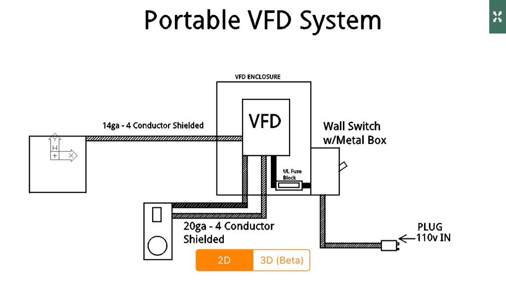
I am gathering supplies and materials to wire everything up. I plan to mount the electrical components on a board which can be plugged into a 15amp receptacle, as I may choose to re-locate the mill as I put it to use. I would like to use the stock Bridgeport FWD/REV switch and a remote potentiometer for speed control. I've read that you should have a fuse and shut-off between the workshop panel box and the VFD, so I am planning to use a fusible disconnect switch.

I drew up the simple wiring diagram to get started with the basic layout. Can anyone weigh in on this? Am I headed in the right direction?

b5d7182e57ff7fdddf708a66e8c4cc9e.png
 
Electrical diagrams are usually drawn with input on the left side, flowing towards the right. Are you going to provide a see-thru window to watch the red led display, cooling fan for air flow, mount the box on the wall? The wires going from the VFD should 4 conductor and shielded. This type of cable looks like regular power line stuff, the difference is that there is a metal braid covering between the inner conducting wires and the outer rubber jacket. Expect to pay more for it too. If it sounds like I'm nit-picking, I'm not. I like working on this sort of thing. You also miss-spelled "ORIGINAL".
 
Electrical diagrams are usually drawn with input on the left side, flowing towards the right. Are you going to provide a see-thru window to watch the red led display, cooling fan for air flow, mount the box on the wall? The wires going from the VFD should 4 conductor and shielded. This type of cable looks like regular power line stuff, the difference is that there is a metal braid covering between the inner conducting wires and the outer rubber jacket. Expect to pay more for it too. If it sounds like I'm nit-picking, I'm not. I like working on this sort of thing. You also miss-spelled "ORIGINAL".

Thank you, nit-picking is always welcome when it comes to detailed work. I just drew this diagram up on a basic CAD application on my cell phone, and wasn't thinking too much about cable type yet. I was going to bend up a box from 16ga steel with a clear acrylic door. Somewhere around 12"x10"x6". I'll mount all the components to a wood board, and then onto the wall so everything can move as one unit. I'll drill out holes in the box for the knockouts and ventilation. I was not going to use a cooling fan, and monitor the temperature. If it seems to get hot, I'll add one.

I was a little unsure of the type of cable to use so that info is very helpful. Is it a solid conductor? I'll have to do some research on what gauge will be right for my application, I imagine a relatively light gauge will be acceptable for this application, but I always error on the side of caution.

Also, spelling is not my strong point...
 
Electrical diagrams are usually drawn with input on the left side, flowing towards the right. Are you going to provide a see-thru window to watch the red led display, cooling fan for air flow, mount the box on the wall? The wires going from the VFD should 4 conductor and shielded. This type of cable looks like regular power line stuff, the difference is that there is a metal braid covering between the inner conducting wires and the outer rubber jacket. Expect to pay more for it too. If it sounds like I'm nit-picking, I'm not. I like working on this sort of thing. You also miss-spelled "ORIGINAL".

As long as we're correcting spelling, you misspelled "miss-spelled". :D
 
You have the general idea right. Diagram looks fine.

It's tempting to use the original ref/off/fwd drum switch but honestly there's no room for
the speed control pot in that switch enclosure. So a new small box with room for a center-off
two position toggle switch, and the 5K ohm pot that's needed, might be a better idea.

The VFD needs overcurrent protection but that could be a simple buss fuse, and the incoming power
again can be a simple toggle switch. So you could save space and money there deleting the fused
disconnect.

Again you need to program the VFD to have it accept inputs from an external pot, and the external switches.
Depending on the exact model, it can throw an error code if you attach the external devices but have not
yet done the programming yet. Not a big deal but read the manual before hand to keep the head-scratching
to a minimum...
 
I was a little unsure of the type of cable to use so that info is very helpful. Is it a solid conductor? I'll have to do some research on what gauge will be right for my application, I imagine a relatively light gauge will be acceptable for this application, but I always error on the side of caution.

Here, try this out. It's what I have in my hand right now. It is stranded wire. I don't think it's that cheap but it least you can get an idea.

http://www.lapptannehill.com/wp-content/uploads/2014/02/OLFLEX_FD-890-890-CY.pdf

A GOOD input line filter before the VFD. There is probably one in the TECO, how good is it? Also, the external wires to the potentiometer can be within a shielded multi-conductor.

Error on the side of caution is what I call over building, which is good. Is my spelling doing better?

"Overbuilding" is one word. ;)

Nice wire in your link. Where would you get that? I used 18 gauge stranded and shielded for my VFD control wiring, but it was cheap wire from Home Depot. My AC line to the VFD is grounded but not shielded, and the wires from the VFD to the motor are not shielded. I get quite a bit of radio interference when running my lathe.
 
+1 on the shielded wire on the output, when you have no shielding, you are creating a nice little local radio transmission antenna. Unlike shielded control wiring, you ground BOTH ENDS of the power cable shielding. You want to create what's called a "Faraday Cage" around those conductors so that nothing gets OUT. With control wire shielding, you are wanting to prevent anything getting IN to those low power circuits.

If you can't find the shielded VFD cable, you can use steel conduit and regular loose stranded wire. Just make sure the steel conduit is bonded to ground as well.

You don't need shielding on the power SUPPLY wiring, but if you still get a lot of RF interference from your VFD, you can get an EMI/RFI Filter unit for it. Most VFD mfrs sell them for their drives, some build them in. There are after market sources as well. Here's one:
TCI, LLC - KRF EMI Filter
 
"Overbuilding" is one word. ;)

Nice wire in your link. Where would you get that? I used 18 gauge stranded and shielded for my VFD control wiring, but it was cheap wire from Home Depot. My AC line to the VFD is grounded but not shielded, and the wires from the VFD to the motor are not shielded. I get quite a bit of radio interference when running my lathe.

I'm an engineer not a English major. You should see how many times I re-edit (Ha Ha, not reedit) posts. Especially due to fast typing. I'm using Firefx speling chcker. (Ha Ha). Seriously, if I screw up then let me know. Not as seriously, I want my posts to read clear to the Communist Chinese Party officials who are monitoring this site. All in the interest that they learn good English so they can set good examples to their subordinates or write VFD manuals. :D

Try these to start.
Multi-Conductor & Paired Cables | Mouser

http://www.digikey.com/product-sear...t=0&page=1&quantity=0&ptm=0&fid=0&pageSize=25

Electronic surplus stores. If a company buys 100 feet and only uses 90 feet the remaining 10 feet can go out the back door on a pallet wrapped in plastic. Pallet wrapped plastic stuff is sold off by the pound, so it can be pretty cheap at the surplus store. I go to HSC in Sunnyvale.
 
+1 on the shielded wire on the output, when you have no shielding, you are creating a nice little local radio transmission antenna. Unlike shielded control wiring, you ground BOTH ENDS of the power cable shielding. You want to create what's called a "Faraday Cage" around those conductors so that nothing gets OUT. With control wire shielding, you are wanting to prevent anything getting IN to those low power circuits.

If you can't find the shielded VFD cable, you can use steel conduit and regular loose stranded wire. Just make sure the steel conduit is bonded to ground as well.

You don't need shielding on the power SUPPLY wiring, but if you still get a lot of RF interference from your VFD, you can get an EMI/RFI Filter unit for it. Most VFD mfrs sell them for their drives, some build them in. There are after market sources as well. Here's one:
TCI, LLC - KRF EMI Filter

This is a 2hp KB Electronics VFD (240v single phase input) running a 2hp 3-phase inverter-rated motor. I used 12 gauge stranded with ground (4 conductors). What shielded cable would be appropriate for this use?
 
Wow. Lots of good info here, thanks guys. I'm going to get a list together and order up the shielded cable and all the other components. I checked my local surplus store for shielded cable, but he only has 24ga. I think I might stick with the fusible disconnect and original fwd/rev switch, and make a separate pod to hold the POT in a convenient spot. I'll think it over a bit.

Meanwhile, I built my enclosure for the VFD. It's 12"x10"x6" which exceeds the space requirements outlined in the VFD's manual. I didn't want to buy an overpriced electrical box and then still have to make a clear door. I need to get a piece of acrylic for the front that will slide in from the top. I'll also add additional vent holes in the bottom and sides as needed. I figured that it will be hanging on my shop wall so I should at least make it look decent.

be53c4bb2d7bd36d3b441c3a099f754b.jpg
 
Awesome electrical box. I would not use a wood panel to mount things to. Recommend metal panel. Don't go crazy ordering and buying until you have the documentation right in front of you. Where is the main distribution panel coming in from the street power? Are you connecting into this distribution panel or a secondary panel? It makes a difference in your wiring method for your VFD where the power comes from. THHN type wire is great for what you are doing for power connections and can be bought by the foot at building supply stores. I would not use rubber or extension cord wire, it deteriorates when exposed to certain atmospheres and lighting. Use stranded wire. If wire terminals will take it use #12 but #14 certainly adequate in the short runs you have. Shielded twisted pair wire will be minimal in your setup, again don't buy 100 feet of it, you can do other ways as has been explained with metal conduit. I agree on the non use of the Fused switch box. Wait and study further.
 
After reading through everyone's advice and some more research, I've modified my plan. I can order shielded cable from McMaster in 5' increments which will save money, so I will order some 14ga for the motor connection and 20ga for the fwd/rev and pot connections. I know the switch and pot doesn't need all four conductors, but I can get 4 conductor cheaper than 3 conductor. Instead of the fusible disconnect, I've decided to use a standard wall switch attached to the side of the VFD enclosure box and a simple UL class fuse block with a 3amp fuse. As I mentioned earlier, the bridgeport's location might change in my shop once I start using it, so for now I am going to run a 14ga plug to a 115v outlet in my shop. My workshop is a detached garage with a sub-panel. The outlet that I am plugging into is a 4 gang that has its own dedicated circuit, not daisy-chained to other receptacles.

How does this look?

1e392d65a9a59d0ba6241e4240548602.png
 
Awesome electrical box. I would not use a wood panel to mount things to. Recommend metal panel. Don't go crazy ordering and buying until you have the documentation right in front of you. Where is the main distribution panel coming in from the street power? Are you connecting into this distribution panel or a secondary panel? It makes a difference in your wiring method for your VFD where the power comes from. THHN type wire is great for what you are doing for power connections and can be bought by the foot at building supply stores. I would not use rubber or extension cord wire, it deteriorates when exposed to certain atmospheres and lighting. Use stranded wire. If wire terminals will take it use #12 but #14 certainly adequate in the short runs you have. Shielded twisted pair wire will be minimal in your setup, again don't buy 100 feet of it, you can do other ways as has been explained with metal conduit. I agree on the non use of the Fused switch box. Wait and study further.

Thank you. I've updated my plan, and posted the new diagram. McMaster sells the shielded cable in short lengths, so I shouldn't have a lot of waste. I've explained where the power is coming from in the updated diagram post. Admittedly, I don't know how coming from a sub panel to receptacle affects the VFD vs coming direct from the main distribution panel...
 
Your 60 cycle power is provided to you as a nice clean sine wave. When it gets to the VFD, the power used by the VFD is not a steady draw but rather chunks taken from the sine wave. If you connect the VFD directly to a Main panel it will be working against the utility's ability to provide clean power (nice sine wave)and that power is really clean and difficult to screw up with the load being so close to the supply.. The further you get your power from the main the more difficult it is to get clean power. So if there are sub panels along the way, the power supplied can get worse. In a main panel you have a main ground buss. This is the location of all grounds. You should never have a ground rod, plate, pipe, not tied directly to this point. When you add panels from the main, the grounding and grounded conductors are separated to prevent grounded conductor currents from flowing on the grounding conductors. So clean power, great grounds, gives the VFD a chance to survive. That's a pretty brief explanation of why I asked about where your feed is coming from.
 
Take a close look at the conductor count for the speed control/pot box.

Four might not do it?

The pot is across the low voltage dc control buss at one end, ground at the other end.
Including the wiper, that makes three wires.

I forget if the switch has the common tied to ground or +V, but that's not another wire
because you have both those there for the pot.

But both ends of the switch have to get to the VFD, that's two more.

So you will need at least five wires I think.


Back
Top