What's new
What's new

Braking HY

user27

Plastic
Joined
Dec 17, 2016
Evening All,

I'm sure it must be here somewhere but I can't for the life of me find out how to fit braking resistors to these cheap import VFDs. I'm generally very happy with them (especially for the price) but a few less seconds of spinning when I hit the estop would sure be nice.

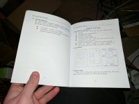
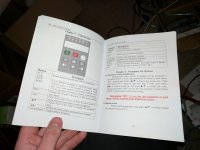
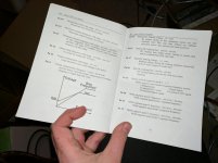
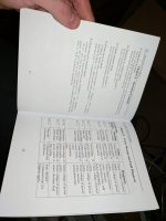
As expected the manual (while containing some delightful chinglish) is of minimal use; it just says "fit components".

The best info I have actually found is a YouTube video showing one of these things in action with external braking resistors glowing red hot under fast deceleration so I know it can be done.

Could somebody point me in the right direction here?

Many thanks
 
There are really FOUR issues.

1) What value of resistance? There is a minimum below which the VFD will be damaged, and the manual should give that value.

2) What power capability is required? That is how you avoid the resistors glowing red hot, which generally is not how it is supposed to work. Again, the manual should give guidance on that. The needed power will vary depending on how much "rotating mass" is involved, but if you just go for the maximum capability you will be fine. The maximum can be calculated.

3) What type of resistor is needed? Some resistors can "take" a considerable overload for a short time, others cannot. Normally the braking resistors are supposed to be a type that can, because they are normally overloaded short term, but operated below maximum power on average. For example: a 200 watt resistor may accept 2000 watts for a second or so, and then, if it is not asked to accept any power for 19 more seconds, the average power is only 100W, well below the rating. But it has to accept the 2000 W without failing. The manual should suggest a type, but may leave that up to you. Sometimes the seller offers resistors, and for the cheapo chinese VFDs, sometimes those really are the right ones....... or not.

4) Finally, where do you connect the resistor? The manual HAS TO TELL YOU THIS.

I have been tempted to class the cheap chinese VFDs in with the "forbidden brands" of machine, but even industrial folks seem to buy them, so......

If you have a link to a manual we may be able to find your info.
 
I think "manual" might be a bit of a generous term... More like panflet.

I don't have it digitally but I do have a camera:
 

Attachments

  • IMG_20170218_001847.jpg
    IMG_20170218_001847.jpg
    87.2 KB · Views: 423
  • IMG_20170218_001904.jpg
    IMG_20170218_001904.jpg
    83.5 KB · Views: 266
  • IMG_20170218_001911.jpg
    IMG_20170218_001911.jpg
    90.1 KB · Views: 226
  • IMG_20170218_001917.jpg
    IMG_20170218_001917.jpg
    86.2 KB · Views: 190
  • IMG_20170218_001925.jpg
    IMG_20170218_001925.jpg
    89.3 KB · Views: 315
I know what you mean about these things; but I just can't get over the price hike on branded ones.

I'd probably pay double for the same VFD with a decent English manual and a support help line (in English); but even for a half decent brand using the exact same chips from the same factory they are upwards of 4x the price.

Frankly I'm surprised nobody has taken the initiative and filled the gap in the market yet. Like you say big industry in buying these things as disposable because it's cheaper in man hours and easier just to swap it out for a new one. If I can't get the estop breaking down to a couple of seconds with a resistor then I might have to bite the bullet and buy a proper inverter.

For reference I paid £140 for a 2.2kw water cooled four bearing router spindle and this 3hp inverter. I'm also using the inverter to drive my lathe since I'll not be using them both at the same time; if it gets annoying switching settings then at this price I can just grab another one.

Sheets 6-10:
 

Attachments

  • IMG_20170218_001932.jpg
    IMG_20170218_001932.jpg
    89.7 KB · Views: 175
  • IMG_20170218_001940.jpg
    IMG_20170218_001940.jpg
    91.8 KB · Views: 137
  • IMG_20170218_001948.jpg
    IMG_20170218_001948.jpg
    93.1 KB · Views: 149
  • IMG_20170218_002013.jpg
    IMG_20170218_002013.jpg
    88.3 KB · Views: 219
  • IMG_20170218_002023.jpg
    IMG_20170218_002023.jpg
    89.3 KB · Views: 180
Glowing red hot braking resistors does not sound like a good idea.
I have 2 name brand VFD's retrofitted in machines, and I used regular electric range elements with great sucess. Neither glows, slightly warm to the touch at best. Installed well over 10 years now.
And cheap!

PS, not sure if they still do it, but at one point Haas VMC's also used electric stove
elements as breaking resistors. In a yellow cad plated box on top of the control cabinet.
 
Sheets 11 through 14... and yes that really is all of it!

Edit: page 18 chapter 9 OU-d error "add braking components" is all I have found.
 

Attachments

  • IMG_20170218_002031.jpg
    IMG_20170218_002031.jpg
    91.2 KB · Views: 214
  • IMG_20170218_002041.jpg
    IMG_20170218_002041.jpg
    92.6 KB · Views: 177
  • IMG_20170218_002054.jpg
    IMG_20170218_002054.jpg
    92 KB · Views: 170
  • IMG_20170218_002103.jpg
    IMG_20170218_002103.jpg
    85.5 KB · Views: 156
Glowing red hot braking resistors does not sound like a good idea.
I have 2 name brand VFD's retrofitted in machines, and I used regular electric range elements with great sucess. Neither glows, slightly warm to the touch at best. Installed well over 10 years now.
And cheap!

Agreed. Assuming that the ohms check out for the VFD then I imagine an old tumble drier heating element would work great!

Thanks for the tip
 
Well, the WHERE to connect is clear enough. P and B seem to be the terminals for the resistor.

WHAT resistor to use is another matter. As mentioned, too small a resistance will blow the braking IGBT, which may be non-replaceable. Sove elements, IF OF PROPER RESISTANCE are a perfectly good option, they clearly will accept high power surges.

And, that unit being an Isacon, apparently, there may be other issues. Someone recently asked about one of them, and apparently they are a special version of the Huanyang, made without many of the standard features, and intended only to operate the Isacon high speed spindles.

It may not have what you need for your lathe application, although it should work for the spindle drive.

The Huanyang units in general are not highly regarded..... the ones I have seen the insides of were not made to any sort of industrial standard at all.

You would do better with an Invertek, which are more-or-less local to you, and not too expensive.
 
Sorry I must be losing my mind; can you tell me where are P and B mentioned please? I have been over every page and come up with nothing.

At this kind of price I could stand to experiment a little running heating elements in series to increase resistance then reduce until I get the kind of braking I'm after.

I have seen plenty of Invertek stuff and it's all nicely done very sturdy IP rated and everything; but they are four times the price for the same chip and it just doesn't sit well with me. Like I said I could understand maybe double the price but where does the 400% markup come from?

This thing does run the lathe no problem and surprisingly high torque right down to single figures in hz no tripping under power; it just hasn't got anywhere to dump the energy when I'm trying to slow it down.

It has crossed my mind that I could take the relay output which comes on during deceleration and use it to switch a resistor right across the DC bus...
 
Page 6. top of diagram. Should be brake resistor, dunno what else it would be.

Last pic of first set.

Either Invertek is a lot cheaper over here, or that issacon was REALLY REALLY cheap. I DID know the Invertek USA guy, though...... Did some work for them.
 
Page 6. top of diagram. Should be brake resistor, dunno what else it would be.

Last pic of first set.

Either Invertek is a lot cheaper over here, or that issacon was REALLY REALLY cheap. I DID know the Invertek USA guy, though...... Did some work for them.

As above I paid £140 for 2.2kw water cooled spindle with the inverter; can't see the single anywhere for less than £100 so it's a £40 inverter where the Inverkek is £200+ I think I found the 2.2kw for £230 delivered.

Thanks very much I hadn't looked at the three phase diagram since I'm running it off single phase; but that does look very much like a brake resistor.

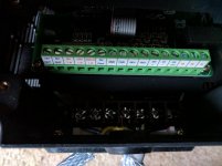
Unfortunately I can't find P or B terminals as below.
 

Attachments

  • IMG_20170228_163953.jpg
    IMG_20170228_163953.jpg
    83.3 KB · Views: 248
If yours is the single phase version, the brake resistor seems not to be an option. P5 is single phase input type, P6 is 3 phase input type.
 
Seems like I have half and half; I have three phase input RST with label "please connect R and T for single phase power" but I don't appear to have P or B terminals. But would I pay 5x the price for better documentation? Still a no I'm afraid.

Anyhow it is what it is; would you care to guess the outcome if I connect a breaking resistor (tumble drier heating element) across the DC bus capacitors via the deceleration relay output?


Thanks
 
It would not be good.

The braking resistor is not quite what it sounds like it would be. It sounds as if it would directly affect braking, but it does not. It affects braking INDIRECTLY.
.
When the VFD slows the motor, current (energy) is pulled OUT of the motor and returned to the bus capacitors in the drive, which are then charged to a higher voltage. The returned energy is used just as any other power is used by the drive.

Only if the returned energy is MORE than can be used, does the braking resistor come into play. It simply bleeds off some of the stored energy from the bus capacitors.

The way that is done is to turn on the resistor for a short time on a schedule.... so it might be on 2% of the time, or 5% of the time. That may be a setting, or it may be dependent on voltage, but the resistor is not applied at all unless the voltage is too high. For many stops it may be un-needed and never come on even if it is a unit with the resistor connections and all the proper circuitry.

The relay in the VFD is not rated for the usage, and in any case, you do NOT want the resistor connected unless it is needed.
 
I'd use the tiny relay to turn on a big beefy one to handle the high voltage DC. But I see your point you don't want it on the whole time that the thing is decelerating.

What are the chances that somebody makes a little dodad that flicks a relay on at a set voltage? You know £0.99 bare PCB delivered direct from China type of deal.

Edit: I could just drop the DC bus voltage with a potential divider and stick the resulting voltage into a transistor which could be adjusted to kick in at say 110% of the normal DC bus voltage. Then just use that to switch a little relay or MOSFET which could be used to drive a big beefy relay connected to the braking resistor.

What do you imagine would happen with that setup? I'd have to get a pretty high resistance multi turn pot.
 
I could just drop the DC bus voltage with a potential divider and stick the resulting voltage into a transistor which could be adjusted to kick in at say 110% of the normal DC bus voltage. Then just use that to switch a little relay or MOSFET which could be used to drive a big beefy relay connected to the braking resistor.

All that sketchy effort because you're too cheap to
buy a better VFD with the features you need built in....
:skep:
:nono:
 
So you know why they are 500% more expensive for the same chip? It's the principle of the thing more than being cheap.

I'll gladly drop a grand or two on tooling if it's worth it. But when it's the exact same chip it is just a rip off to quadruple the price to write a decent English manual.
 
Just curious if you ever got the braking resistor connected and working. I just picked up an HY 2.2kw 3hp VFD for $140 to use on my 2hp Tree Mill and it works great. Am using the acccel. and decel timings to slow it down using the built-in mechanical brake on the spindle motor. I want to switch to using a braking resistor so I can scrap the mechanical brake, as it is 3 phase and for sure can't be powered off the VFD. Then I wouldn't have to use the rotary phase converter.
 
Here's an idea, not foolproof but fits with the on-the-cheap approach with these VFDs and has some basis in past practice in other settings. Stove and dryer heating elements are high wattage, low resistance. Low resistance means it'll pull high current from your drive, which is rolling the dice with the drive innards if the heating element is too low a resistance compared to the drive's intended/design brake resistance rating.

The suggestion: Radio transmitter testing requires a "dummy load" which is a resistive element. The improvised way, when lacking the proper and precise high-watt precise resistor is... an incandescent light bulb. It's a shoddy solution that, with the right size lightbulb, works surprisingly well. The light bulb even has a bit of a self-moderating effect because as more power flows through it, the resistance of the filament increases from the heat. If I remember correctly, 120 volt light bulbs in the 60-75 watt vicinity have a resistance vaguely in the 50 ohm region, which is safely higher resistance enough than the stove/dryer heating elements that you aren't rolling the dice in a big way on drawing too much current through your drive's innards on your first try. If you want to be extra conservative, start off with smaller wattage bulbs to start, being lower wattage they are higher resistance and will not draw as much current from the drive. There is some risk that too small a bulb (which = too high a resistance) will not bleed the voltage off fast enough and your bus capacitors will take the strain of the resulting voltage spike.

String two 120v light bulbs in series to get a 240v resistance load. If the spike of voltage that the drive is trying to dissipate is higher voltage than the regular bus voltage (but I would assume that the drive, in dumping into a resistor, is trying precisely to prevent such an above-bus-voltage spike), string 3 bulbs in series to get a 360v capable load. The series connection of the bulbs also multiplies your wattage-dissipation ability- two 75 watt bulbs in series are capable of dissipating 150 watts, and so on.

The brightness and duration of light from the lightbulbs will give you feedback on whether your bulb size is on or off the mark. A longer glow suggests that the bulbs are undersized and not bleeding the voltage away fast enough. Too big a bulb/ too low a resistance equals a short flash and maybe a burned out lightbulb (which might act as a fuse to limit current out of the drive)(though once the filament expires, but then your bus capacitors may have some un-dissipated voltage to contend with).

If I were going to do this, I would probably start with a series connected pair of 75 watt bulbs, which should give you somewhere in the neighborhood of 100 ohms (which if I recall is in the neighborhood of what some mid-size drives I've looked up expect as a load resistor, although I looked that up some time ago), at somewhere around 150 watts dissipation, and capable of handling 240 volts.

I see that the original poster is in the UK and if I remember correctly your native voltage there is 200 or so so maybe you don't even need to series-connect the bulbs. But you have to do some figuring about the wattage because you've got different voltage and current. If using a 240v bulb I'd probably start at around a 100-150 watt bulb (or a couple of 60-75 watt 240v bulbs in parallel)

This is a total bubblegum & bailing wire approach, but not much more so (and in my opinion, less risk) than the dryer or stove element, and you can't beat the cost of entry of a few lightbulbs and a few cheap lightbulb sockets, and you get the visual feedback from the brightness and duration of the light, so that you can go visit your friendly neighborhood resistance-load-shop (any store that carries lightbulbs) to do some resistor comparison shopping.

YMMV and 100% at your own risk, etc. Don't put the lightbulbs near your face or other valued body parts while under test or in use just in case they do a dramatic flashbulb performance, etc.

PS, trying to measure the resistance of an un-lit lightbulb with an ohm-meter/multimeter is a fairly useless exercise, because the cold unlit resistance is significantly different from the hot /lit resistance. And: though this is stating the wildly obvious to anyone who knows enough about electricity to have any business messing with a VFD, but with the internet you never know who could turn out to be the eventual audience, this only works with old-school inefficient incandescent lightbulbs- compact florescent or LED bulbs will be stunningly unsuited for this use, for the sake of both the VFD and the bulbs, and their inner electronics may behave more like firecrackers.


Back
Top