What's new
What's new

Can you Run a three phase Transformer from single phase?

alastairseggie

Aluminum
Joined
Jun 26, 2013
Location
UK
Hi All

I recently purchased a Bridgeport R2E3 CNC machine. I have so far managed to repair the damaged circuit boards and the blown PSU I have single phased everything except the Motor which I have running (very roughly) using capacitors. I intend putting an inverter on this and it all works.

Now the servo Drives are fed from a three phase transformer which is giving me a headache. Here is the plate info and a pic of the physical transformer:

photo (1).jpgphoto (2).jpg

The primary has two windings which are used in the 230v config. These are run in series for 460V and in parallel for 230V as given on the plate data. My thinking was to common up X1,Y1,Z1,X3,Y3,Z3 and connect the 230v single phase live there then common up the X2,Y2,Z2,X4,Y4,Z4 and connect the neutral.

This just tripped the breaker.

Next I connected X1 to X3 to Live and X2 to X4 to neutral this draws about 2A, I then decided to add another winding from the Y leg and connected X1 to X3 to Y1 to Live and X2 to X4 to Y2 to neutral this draws 85A and I hit the panic button to switch it off. This makes no sense to me.

With X1 to X3 to Live and X2 to X4 to neutral I get enough from the secondary windings to run the servos unloaded (just the table), but I suspect that if any load was placed on them there would be issues as there would be only 2 out of 6 primary coils providing the magnetic flux.

Can anyone explain what is happening here and why two coils draw 2A and three draw 85A?

Also can what I am trying to do even be done i.e. run all the 6 primary coils in series from a single phase supply?

I have a good electrical and Electronics understanding but this has me beat.

Alastair
 
Visualize the magnetic flux as it circulates around the core. Remember that when it is going up one leg, it is going down another. I think you need to hook two of the coils with one reversed from what you did and leave the third open. Either that or just use one set of coils. Can you post picture of the transformer nameplate? It probably has the standard line transformer connections, but it would be useful to see. In any case, it isn't a very good idea from the viewpoint of efficiency.

Bill
 
Last edited:
I agree with Bill. Since the transformer is now just feeding the controls and not the motor also, I would swap out the transformer. If you do plane to use the existing transformer, remember that there is voltage and power available from the unused coil. Don't let something touch just because it not used.

Tom
 
Bill

Thanks for that I thought it might be related to the magnetics. I attached a picture of the Name plate and a pic of the transformer. Can you not see it? Perhaps I have done some thing wrong. Here it is again.

photo (1).jpg

Tom, The transformer is supplying 3 x 70vAC to the rectifiers for the 100vDC needed by the XY and Z servos. It is huge in three phase form if I were to change it out for a single phase it would be even bigger and I suspect very expensive! It is about a food high by a foot wide and a foot deep weighs 32kg (70lb). Got you on the other coils they are isolated thanks.
 
I seem to recall that you can run a 3ph transformer in 2ph (single), but it requires the taps to be brought out so you can make 2 phase inputs by pulling from either side of a center tap in the middle phase. I don't see that being doable with this transformer.

The bigger issue is that your servo drives are 3ph, which means that if you run them off 1ph, you will lose 30% of the power supply capacity, which can result in damaged components if you run it too hard. At best you'll just take 30lb servos and make them weaker because less current availability. Truth is, you probably won't push the servo power supply (assuming it is 1 PS feeding 3 servos) too hard in hobby use.

I recommend another transformer because you will be fighting the magnetic flux if you try and use 2 of the 3 ph inputs.
 
The input windings are connected in delta. You might be able to connect X3 to Z4 as shown and Z3 to X4 with the 240 V to them, leaving Y disconnected, but all it would do is divide the load between windings. Since both would be on the same phase, only one set of rectifiers would be active. If the servos are DC, you would have low torque, but they probably would run to some extent. Replacing the transformer with a single phase one will not really help. If they are AC servos, you won't have much. Why don't you take the coward's way out and get a phase converter?

Bill

P. S. The first picture only appeared this time. In the past, it was not visible. PM has done some strange things since changing servers.
 
Bill

The transformer is supplying 3 x 70vAC to the rectifiers for the 100vDC needed by the XY and Z servos. It is huge in three phase form if I were to change it out for a single phase it would be even bigger and I suspect very expensive! It is about a food high by a foot wide and a foot deep weighs 32kg (70lb). Got you on the other coils they are isolated thanks.


we do retrofits like this. often design engineers do not realize power in = power out and so go by simply adding up x,y,z drive CURRENT ratings and then pick a transformer with that curent rating... IIRC I saw 15amps per ph on the output of ur xfmr so 15*80*1.73=2.1kw..... so if each motor is same size, that means u can power upto 700watt motors...... bet u dont have 700watt motors :)

what goes up must come down..... ie., if you go full rapic traverse up to speed, then decel, you weill average power usage. likelise, most folks machine (hi torque=hi curent) at low speed like less than 1/5 max; hence input current is 1/5 what goes into the motor.

bottom line: just power 1 phase (or 2 reversed like 9100 told u) and TRY IT - BET U LIKE IT! go to harbor freight, spend $ 22 on an IR temp gun: point at xmfr now and again as you do worse case machining like this AND SEE IF IT IS OVERHEATING! bet not.
 
Mike - Servos are DC, Name plate details below:

photo (3).jpg

Bill - I thought Phase converters were a bit of a no-no with electronics or is that just using VFD's to give you three phase? I would really not want to go down that route unless it was my last option.

Alastair
 
You might examine the so-called "Haas-Kamp" connection.

In this connection, the first primary is connected normally, but to the single-phase source.

The third primary is connected in reverse, also to the single-phase source.

The middle primary is connected to the single-phase source through a pair of run-type capacitors, one in each lead.

This connection has been successfully implemented on quite a number of presumed three-phase-only welders.
 
the cont amp rating is missing off the motor naemplate shown so cannot comment. part no is obscure (in shadow) so I cannot look it up to get Ic rating for you. best guess is 3nm(2.2#-ft) @ 4000 rpm means 2.2*4000/5252=1.67hp = 1200watt each /90vdc= 13amp cont guess.

so u cut metal right? at 4000rpm? prob not. prob at less than 1000rpm. so the power to the motor will be 1/4 the nameplate max or 300watt. will you cut with all 3 axis at the same time? prob not, so say 2 axes, so 600watt total likely worse case.

so you got 90vdc input (ok round the 80vac or 70vac) so 600w/90= 6.6amps.....

Now think your single 15 amp winding STILL is too small? Prob not..... go for it. Don't waste money on a new xfmr yet....
 
Ok, we are closing in on this. Phase converters might be a problem with electronics. The first thing I would check is whether the electronics are run off all three phases. I would guess that they are not and can be connected to the real phase only. Next, are the DC servos simply run off a + and - DC supply and if so, will the DC still be clean enough on single phase. If you use full wave three phase rectification, you have only about 14.4% difference between peaks and low points without any filtering. If they are using such a system and you only feed it one phase, you are going to have 100% ripple and your motors are likely to buzz. My Boston Digital mill has SCR drivers, basically three phase light dimmers. You can hear the hum but the pulses are close enough together that it doesn't print on the work. Running that system on single phase with only 1/3 the pulses would really be ragged.

I keep threatening to design a phase correcting transformer that would balance the voltages and phase angles of anything that sort of looked like three phase fed to it. I have one sketched out, a bunch of windings and improbable vectors that blend all the phases to bring everything fairly well into line.

Bill
 
Mike the servo motor is a SEM MT30M4-24 Data sheet here ----> https://www.dropbox.com/s/2g1m3viq0jlf1yx/MT_Technical_Data_Manual.pdf
Very good guess! the Continuous stall current is 13.6A and I am sure you are right I wont be doing too much heavy milling.

Bill

The first thing I would check is whether the electronics are run off all three phases.

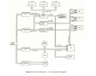
Below is the power distribution Diag from the Installation and Maintenance Manual. It details an overview of what goes where and at what voltages. I have full wiring diagrams if you think that would help. From those the two other control transformers are fed form L1-L2 and L2-L3. I have now single phased these.

r2e3 Power.jpg

Next, are the DC servos simply run off a + and - DC supply and if so, will the DC still be clean enough on single phase. If you use full wave three phase rectification, you have only about 14.4% difference between peaks and low points without any filtering. If they are using such a system and you only feed it one phase, you are going to have 100% ripple and your motors are likely to buzz.

Below I have also attached the Schematic for T2 (the 3ph transformer) showing the rectification. It seems to all go to a common DC rail after the Three phase transformer hence why the servos work with just one coil. They have the voltage but not the Amps. The clip of the schematic shows the Y axis Drive connections X and Z are identical. The drives do Whine (not buzz) but I am not sure if this is because of the single phase. I bought the machine as a non runner so have never had it on 3 Ph. Drives are CSR contraves NC414 (model no A1520) manual can be found here https://www.dropbox.com/s/15x4jbcf8g7c5ii/NC400%20Servo%20Controller%20OM%20%28M502001_d%29%20%282%29.pdf

T2 wiring.jpg

I keep threatening to design a phase correcting transformer that would balance the voltages and phase angles of anything that sort of looked like three phase fed to it. I have one sketched out, a bunch of windings and improbable vectors that blend all the phases to bring everything fairly well into line.
Bill

Care to share your musings/Sketch?

Alastair
 
The next question is how good is the DC under load? There are three capacitors across the DC output, so the DC is probably fairly good with a light load. The question is how much ripple do you have under a heavy load and how tolerant is the driver regarding ripple? Since there is no center point with positive and negative supply, the connections to the motor must be reversed electronically. A regular analog control with the transistors dropping the voltage as required would need huge transistors. The killer is a slow heavy cut. The supply is still delivering 80 VDC or so, but you only need a few volts to the motor, at a high current. The transistors wind up dropping 70 V at 10 A, dissipating 700 watts, but not for long. My guess is that the drivers are H bridge switchers and the whine you hear is the pulse repetition rate. A further guess is that the servos will be all right at light loads where the ripple is low but will get cranky with a heavy one.

Re phase correction transformers, If you connect secondary windings on all three legs in series with one flipped from the way you would normally connect it, you get a voltage output composed of all phases added vectorially. Because of the phase angles, the voltage sum will be less than the scalar total of the three voltages, but all will be contributing. Do that with three sets of windings and you will have three phases each made up of pieces of all the input phases. You can also improve balance by playing games between WYE and delta. Mushing all the magnetic fields in a three phase core blends them even more. I only have small three phase cores that don't have windings on them already, but I may make something good for around 1/4 hp to test the principle.

Bill
 
I have an older Bridgeport CNC Mill. Repaired the drivers a few times! However in my machine the Spindle motor is 3 Phase AC Variable speed via belt drive. A motor is used rather than the typical hand wheel to change speed, not sure as I never looked but there might be a tach. to determine spindle speed since spindle speed can be programmed.
I'm thinking you will need 3 phase to drive the spindle motor since that transformer looks a bit small and about the same type I have on my machine. Do you plan to use 2 power inputs?

Frank
 
The next question is how good is the DC under load? There are three capacitors across the DC output, so the DC is probably fairly good with a light load. The question is how much ripple do you have under a heavy load and how tolerant is the driver regarding ripple?

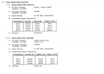
The specs for the drive say different things dependent on the type of transformer. See relavant page below.

Servo drives PS spec.jpg


Since there is no center point with positive and negative supply, the connections to the motor must be reversed electronically. A regular analog control with the transistors dropping the voltage as required would need huge transistors. The killer is a slow heavy cut. The supply is still delivering 80 VDC or so, but you only need a few volts to the motor, at a high current. The transistors wind up dropping 70 V at 10 A, dissipating 700 watts, but not for long. My guess is that the drivers are H bridge switchers and the whine you hear is the pulse repetition rate. A further guess is that the servos will be all right at light loads where the ripple is low but will get cranky with a heavy one.

The best I can do at the moment is rapids as I don't have the spindle drive sorted out yet. I took some readings on the live going to the primaries

Transformer energised 0.68A
Drives enabled 1.58A
1 drive running at 250 ipm (which is the Max for the machine) 2.90A
2 Drives running at 250 Ipm 4.88A


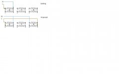
Going over your previous posts I think I understand and I wanted to run this by you before trying it would wiring it as the "proposed" diagram work?

two phased wiring.jpg

Alastair
 
Frank

I have the vari-speed drive which is pneumatically actuated. The motor will eventually end up on a cheap VSD......Or I will put it all back together and get a Rotary Converter! not sure which......Yet!

Alastair
 
The next question is how good is the DC under load? There are three capacitors across the DC output, so the DC is probably fairly good with a light load. The question is how much ripple do you have under a heavy load and how tolerant is the driver regarding ripple? Since there is no center point with positive and negative supply, the connections to the motor must be reversed electronically. A regular analog control with the transistors dropping the voltage as required would need huge transistors. The killer is a slow heavy cut. The supply is still delivering 80 VDC or so, but you only need a few volts to the motor, at a high current. The transistors wind up dropping 70 V at 10 A, dissipating 700 watts, but not for long. My guess is that the drivers are H bridge switchers and the whine you hear is the pulse repetition rate. A further guess is that the servos will be all right at light loads where the ripple is low but will get cranky with a heavy one. Bill

dont jump off the cliff yet..... those drives, CSR contraves NC414, are nice little PWM drives, not linear. so they are not dropping 70v@10amps; they just are turning on the pwm real skinny like to do your HEAVY machining. result is you pull real LOW current from the power supply for the 13 amps into the motor at 1/10 or 1/4 top speed.

You will have no problem with ripple voltage due to 1ph input on the system you have described. we have done this a zillion times in the last 35+ yrs. ur only issue would be if you tried to machine at full motor speed with really high current - THEN the 60hz 'ripple' would come thru as hum and 60hz vibration - I doubt you could make the machine operate like this; if you did, you would be the first!

I think I got a few of them CSR drives in the warehouse. If one of yours breaks maybe I can help you out for a nice 30 pack of icehouse.....
 
Going over your previous posts I think I understand and I wanted to run this by you before trying it would wiring it as the "proposed" diagram work?

View attachment 83082

Alastair

That should work, but for my own peace of mind, please disconnect the secondaries before lighting it up. I have never done that and am fairly sure what will happen, but there is always a sliver of doubt.

Bill
 
dont jump off the cliff yet..... those drives, CSR contraves NC414, are nice little PWM drives, not linear. so they are not dropping 70v@10amps; they just are turning on the pwm real skinny like to do your HEAVY machining. result is you pull real LOW current from the power supply for the 13 amps into the motor at 1/10 or 1/4 top speed.

You will have no problem with ripple voltage due to 1ph input on the system you have described. we have done this a zillion times in the last 35+ yrs. ur only issue would be if you tried to machine at full motor speed with really high current - THEN the 60hz 'ripple' would come thru as hum and 60hz vibration - I doubt you could make the machine operate like this; if you did, you would be the first!

I think I got a few of them CSR drives in the warehouse. If one of yours breaks maybe I can help you out for a nice 30 pack of icehouse.....


You are confirming what I guessed. It seemed unlikely that they would have a series pass regulator working at that voltage and current. Power supplies in that range typically have a preregulator with SCRs, or whatever. It seemed more likely that they would use some sort of pulsed control. If you look at the basic data of power transistors, it sometimes appears that they will work, but if you look at the curves, there is the little dotted line that says you can't do it. Just to make life more exciting, the transistors usually fail shorted and you go to full power out.

Bill
 
Alastair; What exact model Bridgeport do you have? It's possible I have the same one! When Bridgeport was still in business I purchased the complete set of manuals including all the schematics.
Some of the components have been discontinued, My digital MDI input numbers were not lighting, I had to redesign the circuit so I could use available components!

Frank


Back
Top