What's new
What's new

Chinese wiring conundrum

NormanW

Plastic
Joined
Sep 19, 2014
Location
Split-Dalmatia
Motor wiring conundrum

Wiring on a Chinese motor

I purchased a new woodworking machine for making mortice and tennon joints and planing timber. The machine was made in China and came from India. I can't get help from the vendor, so am working through this myself. There is no manual although with the exception of the wiring, it is extremely robust and appears well made. Built by blacksmiths comes to mind.

When it arrived I checked it over and found that there was just a two pin plug, no earth, with 1.5mm copper cable in a blue and a brown sheath. This looked like lighting cable and for a 2HP motor seemed inadequate.

When I looked inside the plastic peckerhead cover on the motor, there are two red leads and four yellow leads that go to the motor. Connecting the switch to the motor were four leads, two blue and two green and yellow (earth cable), and a green and yellow earth lead that is not connected to anything. There is no wiring diagram. The wiring was not well done with stray copper wire ends coming from connectors.
rear of motor.jpg
motor.jpg
I didn't try the motor in this configuration. Rather, with a circuit tester I traced which wire went where, then put in a new 5 core cable, brown, blue, black, grey and earth from this block to the switch (and a 3 core power lead). Brown is live (one of the blue wires), blue is return and the grey and black replace the two green/yellow leads that were present.

When I turn the switch on, I get loud buzzing from the motor, but no movement. I only try it for a second or two and it doesn't trip the RCD. The motor turns freely by hand. The switch has three buttons, green, black and red. Red is obvious, but I suspect the green and black buttons are about motor speed. Again, no instructions but with the circuit tester the voltage is directed in different pathways according to which button is pressed.
rear of switch.jpg
I have replicated exactly the wiring I found, only with an earth, and normal coloured cables, but clearly something is wrong.

I have tried to locate a company website but failed and although I have the machine name and number, there is nothing on the internet for it. I suspect it was manufactured some time ago, although everything was wrapped in brown wax paper, protected and greased, it just looks so 1960's.

Thanks for reading, any help would be appreciated.

NW
 
Last edited:
Put location in your profile, or you might get kicked.

Part of forum rules...

Look for a similar machine, which actually has support... Grizzly for example.

They have manuals and schematics online..

Chicom motors have a bad reputation, and deserve it....

If machine is worth it, dump motor and replace with a Baldor/ Lincoln/Marathon..
 
Wiring on a Chinese motor

I purchased a new woodworking machine for making mortice and tennon joints and planing timber. The machine was made in China and came from India. There is no manual although with the exception of the wiring, it is extremely robust and appears well made. Built by blacksmiths comes to mind.

When it arrived I checked it over and found that there was just a two pin plug, no earth, with 1.5mm copper cable in a blue and a brown sheath. This looked like lighting cable and for a 2HP motor seemed inadequate.

When I looked inside the plastic peckerhead cover on the motor, there are two red leads and four yellow leads that go to the motor. Connecting the switch to the motor were four leads, two blue and two green and yellow (earth cable), and a green and yellow earth lead that is not connected to anything. There is no wiring diagram. The wiring was not well done with stray copper wire ends coming from connectors.
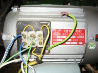
View attachment 117326
View attachment 117327
I didn't try the motor in this configuration. Rather, with a circuit tester I traced which wire went where, then put in a new 5 core cable, brown, blue, black, grey and earth from this block to the switch (and a 3 core power lead). Brown is live (one of the blue wires), blue is return and the grey and black replace the two green/yellow leads that were present.

When I turn the switch on, I get loud buzzing from the motor, but no movement. I only try it for a second or two and it doesn't trip the RCD. The motor turns freely by hand. The switch has three buttons, green, black and red. Red is obvious, but I suspect the green and black buttons are about motor speed. Again, no instructions but with the circuit tester the voltage is directed in different pathways according to which button is pressed.
View attachment 117328
I have replicated exactly the wiring I found, only with an earth, and normal coloured cables, but clearly something is wrong.

I have tried to locate a company website but failed and although I have the machine name and number, there is nothing on the internet for it. I suspect it was manufactured some time ago, although everything was wrapped in brown wax paper, protected and greased, it just looks so 1960's.

Thanks for reading, any help would be appreciated.

NW

Can you confirm the machine is single phase 220v?

Sad experience leads me to suggest that you remove and discard all wiring and switchgear and replace with something trustworthy. Having a push button switch collapse and allow ones finger access to live terminals is not funny.

Oh, and megger test that motor, even if new.
 
This is very very marginal as a topic..... chines chinese and chinese......

Take the chinese out of title, and make it meaningful, or closed it will be.

Split is directly across the Adriatic from Pescara, Italy

It is, IIRC, and at least *was* a nice place to visit... but what's the comment about?
 
Dear JST

Thank you for replying. As requested I have changed the title removing Chinese. I was not sure where to post the question but as there were other questions about motor in this section I posted it here. I apologise if I have offended you or broken rules. Please would you tell me where the question should be posted?

I have no idea what the comment is about, sorry.

NW
 
Dear Greenwud

Thanks for the helpful comments. Yes confirmed single phase, 220v 50 Hz.

NW

Single phase will have a starting arrangement of some sort, usually a capacitor (or two if required for running). Stalling and humming is expected if there is a problem with the capacitor.
 
I don't parse chinese but the motor plate seems to be 2800rpm 220v and 50hz, suggesting a single speed motor. Is there a reason for reversing the motor in the way the machine operates? Looking at the back of the switch, which
you need to do continuity checks on to determine what connects are made when each button is pushed. There seems to be a black wired X on the switch suggesting a reversal there. Looking at the motor I would guess the yellow
motor wires are the start windings and the red motor wires the run windings and there seems to be a capacitor housing on the motor. That suggests the green/yellow leads are supposed to go to the capacitor as they seem to be in series with
the yellow motor wires.
 
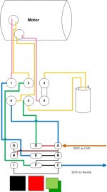
Drawn a wiring route map

I don't parse chinese but the motor plate seems to be 2800rpm 220v and 50hz, suggesting a single speed motor. Is there a reason for reversing the motor in the way the machine operates? Looking at the back of the switch, which
you need to do continuity checks on to determine what connects are made when each button is pushed. There seems to be a black wired X on the switch suggesting a reversal there. Looking at the motor I would guess the yellow
motor wires are the start windings and the red motor wires the run windings and there seems to be a capacitor housing on the motor. That suggests the green/yellow leads are supposed to go to the capacitor as they seem to be in series with
the yellow motor wires.

Thanks for your response. I've done more work on this and have drawn a plan after doing the continuity checks. Yes, it is 2800 rpm 220 v 50hz and built in 1993! I havde also checked the capacitor and get the needle to move right across and settle back at 1 ohm, which I belive means the capacitor is ok. Did the test several times and got the same result.

What I thought were two speeds (one for the morticing drill press and one for the planer), seems to to a direction reverser, for the same two functions.

This is the connection when the green button is pressed. The black crossing wires are shown as thin wires on my drawing:
Motor wiring.jpg

This is the inside of the switch:
inside switch.jpg

What I have found is that there is a permanent live connection, to connector 6 on the pekerhead, even when neither button is depressed, from the incoming mains feed. That seems both unusual and unsafe to me?
 
When I read your description of capacitor checking, I have the impression that you don't know how to do it.
If you have a meter with capacitance measuring capability, this is the way to go.

If you just have an analog ohm meter, you still can tell if capacitor is open or shorted. First of all disconnect one wire from the capacitor. Then with the meter on the lowest ohm range (x1 or x10) touch the capacitor terminals with meter probes and watch the needle. It should swing from infinity towards zero and then go back to infinity. It should not settle at 1 ohm reading.

Check it again and let's hope your problem is just a bad capacitor.
 
Dear JST

Thank you for replying. As requested I have changed the title removing Chinese. I was not sure where to post the question but as there were other questions about motor in this section I posted it here. I apologise if I have offended you or broken rules. Please would you tell me where the question should be posted?

I have no idea what the comment is about, sorry.

NW

You are in the right place.

And now that I see your location , I understand the other comment. I have been there, and it was a nice city 50 years ago.

The owner of the site has some rules (which I do not make, I just enforce them) Thank you for trying to change the title. Unfortunately it didn't work, and apparently even I cannot do it now. I will not close this because it may be helpful.

As for the problem.....

A single phase motor has two windings. One is to run the motor. The other is to provide another "phase" , creating a rotating magnetic field, and actual torque to start the motor. The start winding is connected only when teh motor is not spinning above a certain speed, often around 60% to 70% of full speed.

It would be best if you had a current meter and could see how much current is being drawn when it does not start. If it is a lot, and the motor itself is humming, then probably the start winding is not getting proper power. A bad capacitor can do this.
 
I would replace the capacitor as a first repair. The motor requires the cap to start, then there is a centrifugal switch in the bell housing in the motor that disconnects the cap/start winding when the motor exceeds
a certain RPM, usually a few hundred. You can hear the click of the switch when the motor is turned off and coasts down. Google capacitor start motors for wiring diagrams. Your switch is a reversing switch with
green going one way, black the other and red off, if conventions are observed. Chinese motor caps are not quality controlled, and replacing is advised. If the motor hums and doesn't blow a circuit breaker try
spinning the shaft, sometimes it will kick off then, just suggests there is a problem with cap/switch. Usually a bad centrifugal switch will manifest by a slow running (50rpm or so) motor with a loud hum, if switch
is shorted or stuck together, if open then the motor just hums because there is no starting kick, hence the suggest to spin the shaft. You may be able to sort of repair a bad centrifugal switch by gently filing or
sanding the contacts, exam of switch will give some clue as to reason for malfunction. Don't expect a replacement to be easy to find but worth an eyeball by a motor shop. Yes the direct connection to the motor
is not a great idea as you note, by one side of 220, you need a separate disconnect switch: 2 pole, single throw, rated for motor current, or an interposed relay.

One other thing, the start winding is not designed to be connected to power for very long and may blow, the run winding is stouter wire and will handle the current better, but neither are designed to be connected to
the power line in a non-turning motor for very long, but start winding is more fragile.
 
To diagnose, you NEED a current meter. The kind that has a loop that clamps over the wire.

With it, you check both the capacitor current, and the main winding current.

if capacitor current is low, capacitor is bad. For shorted capacitor, your meter should check that OK.

If main winding current is low, there is a different issue, maybe with a switch or connections.

What I would EXPECT is a main winding current at start which is much more than the labeled running current on the motor tag. The start winding current is more of a question, but should clearly be several amperes at the least.

No need to replace things as a diagnostic technique unless there is no other option.
 
Dear Mikey533

Thank you for your insight. It is not that I don't know how to test, it is that I am confused by the results.

I only have a very basic "hobby" meter. If you look at my drawing of the wiring diagram, I have labeled the two terminals on the capacitor 'X' and 'Z' .

With the meter set on 1 ohm, if I connect the negative lead on the meter to the 'Z' side, when I connect the positive, there is a complete and instant deflection to zero then it takes around four seconds to go settle back to infinity. Doing the same test a minute or so later, the deflection is only one third up the scale to around 20 ohms, then it settles back to infinity.

However, if I reverse the connection, so that the negative is connected to the 'X' side, and touch 'Z' with the positive, there is only a deflection to exactly half way up the scale, to 5 ohms on my meter, then it settles back to infinity. The second test the needle deflects to 20 and settles back.

As there are no markings on the capacitor to indicate if one side is positive or not and I read that some capacitors do not have a positive / negative side, I am unsure what the readings tell me. I also wrote may answer when I was away from home and didn't have the meter in front of me. It was only when I got back and looked at it and saw that there was a minute infinity symbol on the left that I knew why I had been hesitant.

NW
 
Dear Sch

Thank you for a clear explanation. I had wondered about trying to turn the motor and then applying power. I'll give that one a try.

I'm not sure whether the different readings on my meter when I connect to the different terminals on the capacitor is significant, and hope someone here could advise me,

As for the permanent live, as a workshop practice, I always unplug unused machines at the wall. Coming from the UK where all wall sockets are type G and under BS1363 have to have switches, to Europe where we are using Schuko type F, which are unswitched, I disconnect everything that is not in use. The two pole switch as well is a good idea between the wall and the machine.

I have plans for a new workshop rather than using a converted stable, this would have a separate pannel and MCB so everything could be off at the flick of one switch, but that is a little way in the future....

NW
 
Dear JST

Thanks for your response. Apologies for the tardy response, I am still waiting for a permanent connection. Split is indeed a beautiful city and I suspect little changed in 50 years, although I live on an island just off shore, which having few facilities makes it difficult. There is no local 'shop' I can go to!

I don't have a clamp type meter. I will see if I can find someone in the village with one that I can borrow.

NW
 
Norman,
Basic ohmmeter is all you need to check if capacitor is open or shorted. It will not tell you the capacitance or ESR value, but that is beyond the limits of our conversation.
To use the ohmmeter correctly you need to make sure the capacitor terminals are not connected to each other by any wire or resistor or anything else. This is where the requirement to disconnect one or both terminals came from.
Then remove the residual charge by shorting the capacitor terminals for a few seconds with any decent conductor (screwdriver blade will do just fine). Now you can do your measurement.
From your description it looks like the capacitor is not shorted or open, but check it again. Keep in mind that capacitor will retain the charge it received from your meter, so you need to short the terminals to remove this charge before any subsequent measurement can be taken.


Back
Top