What's new
What's new

Disconnect needed between phase converter and transformer?

mmurray70

Stainless
Joined
Jan 11, 2003
I bought a used 35hp phase converter that came with a transformer (220v in and 220v out with taps for a 5% boost or cut to voltage). I guess this also fixes the wild leg problem too right?

Anyway the previous owner wired the transformer in directly and started the converter with the transformer connected, ran like this for years with no problems. I thought phase converters had to be started without any load connected? Should i install a disconnect and only connect the transformer once the converter is up to speed? This should make for less load on the system when starting right? Or should i just use it the same way it has been running for years?
 
In general I would have said yes, best to take ALL loads off first before starting. In fact, I and others HAVE suggested that. But if the load is light enough, and an unloaded transformer could qualify*, then I suppose it could be handled. Might need to adjust the start caps for the added load, might not need to, depending.

Unloaded transformer means not connected to anything on the far side, everything turned off. Anything connected to the secondary would be an added load on the start circuit, and IIRC that may have been an issue in the other situations where the switch was recommended.

It would seem that it could eliminate the wild leg, turning it into either corner grounded (probably) or possibly 3 wire plus neutral. That depends on the way the transformer is set up. I'm not sure there is really any "problem" with the wild leg, nor am I sure corner grounding is much of an improvement. The tapping might be advantageous, especially as there is no obligation to tap all legs the same. Might allow adjusting voltages in case of an imbalance.

* A transformer with no load on it typically draws only about 1% to 3% of its rated VA, depending on size. It DOES have an inrush to establish the magnetic field, which would need to be supplied from the start circuit if it is always connected. The inrush does not last very long, however.
 
Thats a great idea about balancing voltages, i didnt think of that. Heres a pic of the transformer info plate. So looks like the transformer is delta to wye (3 wires plus neutral). Which side is in and which is out? Im thinking delta would be the input and wye out but want to be sure.

If you are not using the neutral wire, is there any difference in delta and wye? The previous owners connections are still on the transformer (they chopped wires on the outside) and neutral was not used and i dont need it either, the adjustable taps are connected to #4 which means equal voltage in and out. Same for all three phases so it wasnt used for balancing.

Do I even need this transformer? Does anything magic happen inside the transformer to clean up or balance the voltage that im missing or is this just using up space and wire for nothing? Both my machines (Fadal 4020 mill and an old mazak 10hp lathe) have transformers that accept 240V input.
 

Attachments

  • 20160718_102932.jpg
    20160718_102932.jpg
    86.6 KB · Views: 314
  • 20160718_102940.jpg
    20160718_102940.jpg
    86.9 KB · Views: 170
Well, the only reason to have it at all is if you NEED to have a star output. otherwise yes, it seems an extra complication.

Balancing voltages I kinda tossed in there, I don't know that it is a very important feature here.

If it come with the RPC, do you know why it was being used?
 
Well, the only reason to have it at all is if you NEED to have a star output. otherwise yes, it seems an extra complication.

Balancing voltages I kinda tossed in there, I don't know that it is a very important feature here.

If it come with the RPC, do you know why it was being used?

If im not using the neutral at all, is the star output even any different then delta? Or is it the exact same thing?

Previous owner did not have electrical knowledge. He said when he bought it he was told the transformer was supposed to make the generated phase better quality. May have just been sales people looking to make a quick buck? Im not sure.

So should I eliminate it from my setup?
 
I'd leave it out unless there is a good reason to have it in. Star or delta with no ground is same thing effectively.
 
The Wye output would be beneficial to VFD type loads, as that is what the standard drive is expecting for input. The transformer coupling could help smooth out the imbalances in the phases. Any 3Φ rectifier load should be better off with a wye supply circuit.

If you you use it, the secondary neutral should be bonded to the case and other grounding conductors.

On the other hand if your machines already contain a 3Φ auto-transformer for adjusting voltage and providing a wye common point, there is not much purpose in having two wye transformers inline with each other.

SAF Ω
 
Both of my machines do have large, built in transformers for adjustable main voltage supply. So im thinking powering direct from phase converter should be fine.

Come to think of it, I dont think the machine that this converter was powering before does have the big adjustable transformer. Perhaps this explains it.

Thanks for the help guys.
 
I got my phase converter powered up. No load voltage phase to phase is 240, 242 and 260. This is with nothing connected. Will this tend to balance off as load is added or do i need to do something to balance things out?
 
I first want to say, I generally start my transformer with my RPC. Not always. But there never loaded on out. I might see a 10th of a second delay trying to start the tranny with RPC. Core saturation might jump me up about one Amp per kVA for 1 seccond.

As for your new voltage totals at idle, they could be all right. I would test loading before screwing around. But ideally, I like to see both naturals to wild being in the 250-ish Mark. I would generally do this with a capacitor. I think the last owner used a transformer instead.

If I'm right, a five dollar capacitor could replace a 300 pound, $250 transformer.
 
Your 260V wild leg is getting near the limit of +/-10% of your 240V line voltage, the limit should be 264V max.
It will drop under load, so you should be OK. Check the taps on both of your machine transformers to ensure that they are set as close as possible to your output voltages.

Try to identify what 2 legs of your machine autotransformers output supply the machine control circuits and connect the wild leg to the transformer line without the control loads.

I would suggest to have the machine disconnect off, start the converter first then energize the machine transformer for less wear and tear on your converter starting circuit. Then before operating the machine check the output voltage of the autotransformer feeding your drives to see if it's within the limits of your drives input specifications.

SAF Ω
 
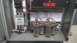
Thanks for the help guys. I had a closer look at this today and it looks like the caps might be wired in wrong. Need you guys to confirm. There are two sets of 3 capacitors in parallel, 6 total. One wire of each set goes to the manufactured leg, the other two wires go to L2, and nothing to L1. Shouldnt there be one going to L1 and one going to L2?
 
Heres a pic showing how its wired. Wire 2 and 4 go to manufactured leg, 1 and 3 both go to L2. Should i move one of these to L1?
 

Attachments

  • 20160801_092415.jpg
    20160801_092415.jpg
    94.2 KB · Views: 403
RPC balancing theory & commercial practice.

I would say not to move them, unless you want to start re-balancing the RPC over again.

If it was balanced enough to use for years in the prior application with no fuss, prolly no foul now. That xformer that came with it, also helped smooth the output some magnetically and you have that covered on your new loads. Can we see a photo of the complete RPC panel build? I liked the cap holder construction.

There is two schools of thought on balancing, balance from one side, or both. Your builder chose from a single line, as I think most commercial RPC builders do. As far as I could tell, the William Fitch design back in 1998 was the one that brought to the fore the idea and methodology to balance from both sides.

There was a few threads covering this in the past, one that I can't find at the moment, where Bill (9100) was saying that, if I remember correctly (correct where needed Bill) you only need to offset the phase displacement from one side, that in effect, offsetting from both sides is not needed or can be counter productive. That makes sense to me when thinking about it from a 120 degree phase relationship. And is also what most builders use.

But the sparky in me, also tends to think in terms of balancing things, on any transformer or circuit, and that the RPC is a like rotary auto transformer. It has a magnetic coupling between stator (Pri) and rotor (Sec), but the input and output winding's are interconnected. Balancing from both sides, would appear to me to be a way of achieving a tighter current balance between the legs, but at the expense of space, time and money.

Maybe we could get Bill and others to rehash this again, for those of us that have never hooked a 3 channel scope to some 240V 3Φ, to have a look see.

SAF Ω
 
From a theory point of view......

Background:

The RPC has some issues that affect its output.

First:

The output is based on the "back EMF" of the idler motor, providing voltage on the wire for the "generated leg". The "back EMF" is typically lower than the mains voltage, because it opposes the applied voltage. The motor speeds up to the point where the difference between the back EMF and the mains voltage allows a current to flow that just provides the required power to operate the motor.

That's a balance that the motor finds, by speeding up or slowing down. As the motor speeds up, the back EMF tends to rise, and as it slows, the back EMF drops. So if the motor requires more power due to an increased load, the back EMF drops with the slowdown, and allows more current to flow, providing more power.

With the idler at no load, the back EMF is nearly equal to the mains volts, because there is virtually no load, and very little power is required. The motor speeds up nearly to synchronous speed, and the generated leg comes up to it's highest voltage, roughly equal to mains voltage.

The back EMF on the other two wires is not very relevant, since they are drawing power from the mains, not supplying it. They draw what is needed as with any motor.

Second:

The fact that only two sets of coils are powered, means that there is some loss as the rotor turns to a position where it induces maximum voltage in the coils for the generated leg. That may reduce the voltage somewhat.

Third:

The idler has some amount of series impedance, a combination of resistance and inductance, due to the coils of wire in the motor. As current is drawn from the generated leg, there is a voltage drop, and a lagging phase shift due to inductance.

So:

Voltage output, and phase, vary with load on the generated output. More load, lower output.

Adding capacitance can cancel the effect of the series inductance, and can even raise the voltage above mains voltage, due to resonance effects. ( The resistance cannot be counteracted in any way, it provides a current-dependent voltage drop.) The net effect is really a form of power factor correction. However, a set value of capacitor can only correct for one condition, and care must be taken not to over-correct for the condition of light loading, which might send voltage way up above mains voltage. It's normal to correct for a high load condition, but not go too far which might bring up the no-load voltage excessively.

So the capacitors can adjust the voltage.

However, they also will cause some phase shift. The shift will be in a useful direction as far as the impedance is concerned, since the inductance will cause a phase lag. Adding capacitance to the output brings the phase back towards a "zero phase shift" condition, theoretically providing close to the 120 degree separation between phases.

The capacitor from one phase to the next will provide a phase-shifted current flow. Splitting the capacitors provides different phased currents from the two phases. So it can be possible to balance the effect toward or away from a particular phase wire somewhat by adjusting the proportion of total capacitance existing between the generated leg and that input wire.

Individual motors might differ in characteristics, and might themselves bias the phase slightly to lead or lag a bit in voltage. I doubt this is very significant. However, splitting the total capacitance between the lines might be able to produce the most perfect combination of phase and voltage.

Whether it is worth going that far is questionable, and will depend on the individual motor. The makers of "generic" RPC boxes for use with a range of motors that are not known ahead of time, likely find it does not pay to get fancy with splitting the capacitors. It can be confusing to the user who is trying to "balance" the RPC, and the extra bit of phase correction is not generally of much consequence anyway.

If for some reason it is found useful to correct the phase closely, splitting the capacitors in that way between phases can be done. It makes little difference as far as the total capacitance, but can allow shifting the phase of the generated leg somewhat with minimal effect on the basic "balancing".
 
I would say not to move them, unless you want to start re-balancing the RPC over again.

If it was balanced enough to use for years in the prior application with no fuss, prolly no foul now. That xformer that came with it, also helped smooth the output some magnetically and you have that covered on your new loads. Can we see a photo of the complete RPC panel build? I liked the cap holder construction.

There is two schools of thought on balancing, balance from one side, or both. Your builder chose from a single line, as I think most commercial RPC builders do. As far as I could tell, the William Fitch design back in 1998 was the one that brought to the fore the idea and methodology to balance from both sides.

There was a few threads covering this in the past, one that I can't find at the moment, where Bill (9100) was saying that, if I remember correctly (correct where needed Bill) you only need to offset the phase displacement from one side, that in effect, offsetting from both sides is not needed or can be counter productive. That makes sense to me when thinking about it from a 120 degree phase relationship. And is also what most builders use.

But the sparky in me, also tends to think in terms of balancing things, on any transformer or circuit, and that the RPC is a like rotary auto transformer. It has a magnetic coupling between stator (Pri) and rotor (Sec), but the input and output winding's are interconnected. Balancing from both sides, would appear to me to be a way of achieving a tighter current balance between the legs, but at the expense of space, time and money.

Maybe we could get Bill and others to rehash this again, for those of us that have never hooked a 3 channel scope to some 240V 3Φ, to have a look see.

SAF Ω

Sorry i have been really busy but here is the pic you asked for. Better late then never
 

Attachments

  • 20160815_134938.jpg
    20160815_134938.jpg
    90.1 KB · Views: 173


Back
Top