What's new
What's new

Haas Kamp Hobart RC300 3 Phase to single phase conversion

jeep534

Cast Iron
Joined
Mar 17, 2003
Location
Huntington WV
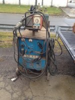
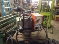
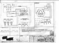
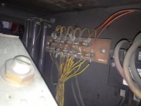
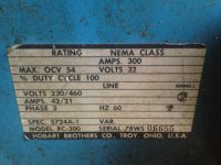
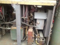
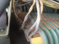
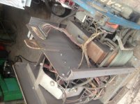
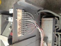
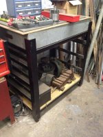
I recently traded for a Hobart RC300 welder with wire feeder. I hauled it directly over to a friends place and we plugged it in put some new wire on it and It welded perfectly it came with a gas bottle and everything. now comes the fun. I have a dedicated 200 amp single phase feeding my shop no 3phase. I am going to give this conversion a try especially since I know this is in working order. here are a few photos. I will take and post a few of the insides shortly.

archie =) =) =)
 

Attachments

  • 1_6_13 002.jpg
    1_6_13 002.jpg
    96.9 KB · Views: 1,917
  • 1_6_13 007.jpg
    1_6_13 007.jpg
    93.5 KB · Views: 1,371
  • 1_6_13 008.jpg
    1_6_13 008.jpg
    92.3 KB · Views: 1,487
as many pictures as i could get without taking the top off. ( I guess that is next)
 

Attachments

  • 1_14_13 018.jpg
    1_14_13 018.jpg
    95.4 KB · Views: 904
  • 1_14_13 019.jpg
    1_14_13 019.jpg
    93.9 KB · Views: 800
  • 1_14_13 024.jpg
    1_14_13 024.jpg
    94.4 KB · Views: 643
  • 1_14_13 025.jpg
    1_14_13 025.jpg
    84.1 KB · Views: 671
  • 1_14_13 027.jpg
    1_14_13 027.jpg
    95.5 KB · Views: 916
more photos
 

Attachments

  • 1_14_13 029.jpg
    1_14_13 029.jpg
    86.2 KB · Views: 546
  • 1_14_13 034.jpg
    1_14_13 034.jpg
    93.4 KB · Views: 551
  • 1_14_13 037.jpg
    1_14_13 037.jpg
    95.8 KB · Views: 495
  • 1_14_13 044.jpg
    1_14_13 044.jpg
    87.2 KB · Views: 934
I found the diagrams, I hope the will help you. I hooked it up using the 220 volt windings A and C and capacitors to B. I used about 240 uF caps. You may want to check with Dave though to see if there is a better way. View attachment 67347View attachment 67348

Thank You.
If you could email the pictures it would be greatly appreciated. I will PM you with the email address. I could not read the thumbnails.

thank you again
archie =) =) =
 
more work on the welder

removed the feeder, gas bottle and top of welder cut ty wraps off of the transformer wires and just finished printing wire tags with a P-touch label printer
here are some more pictures i took today.
 

Attachments

  • 1_17_13 006.jpg
    1_17_13 006.jpg
    91.8 KB · Views: 1,103
  • 1_17_13 007.jpg
    1_17_13 007.jpg
    89 KB · Views: 660
  • 1_17_13 008.jpg
    1_17_13 008.jpg
    89.2 KB · Views: 936
  • 1_17_13 009.jpg
    1_17_13 009.jpg
    88.8 KB · Views: 1,104
Oh yeah- this one is a sweetheart... a big, strong, heavyweight, powerful sweetheart! 300A at 100% duty cycle, and I LOVE that pivoting mount for the wire feeder (I'm gonna steal that idea!). Dual-roller system will feed even AFTER hell freezes over...

TJB's diagram has it right on, and with this one, I believe that absolutely everything you need to alter, is right at the terminal strip... nothing to 'dig out'. Just remove the jumpers that connect the corners, move your power leads, and connect the capacitors feeding "B", and you'll be set. If what I see is correct, TJB has included his observed values for C1 and C2 as 210-240uf (@430vac or higher, and MOTOR RUN capacitors, please...).

Perhaps he can show you a pic of his mechanical installation of the caps, and the source he used... he may have an elegant mounting solution...

thank you dave
I am labeling wires ( make SURE i dont screw up) I am color coding the wires for the run capicators I only have white wire. also I am curious about the name Haas Kemp
and by the way I did put al label inside the welder to that effect.... grin

thanks again.
archie =) =) =)
 
Dave , I don't Know about elegant, I just Mounted them with conduit clamps mounted to the fan shroud with self tapping screws. Sorry I didn,t take pictures of this one. As to the value of the caps, I just kept on adding until it seemed to like it. Asto the source I think it was Surplus Center. The fellow I did this for uses it to carbon arc , probably not the best use but he likes it.
 
Archie- the name Haas-Kamp refers to Peter Haas, and me... (and it's an A, not an E in Kamp)... Peter is a retired power systems engineer who frequents this forum, and he used to work for PG&E. My scholastic background is heavy in electronic, electrical and mechanical engineering, but I avoid offices, and spend my time doing field work. I came up with the concept of phase shifting the middle transformer core to make the H-core shape operate in it's 3-phase sequence, and emailed a photo of the napkin-based schematic to Peter to ponder it. Over a period of a few days, we discussed the theoretical math, and came to the conclusion that it would either work, or fail, survive or burn... and since I had a CP200 sitting in my garage, I dug into it, and after some tinkering, found that it worked as planned.

And that's the rest of the story.
 
Thank you Dave,
I am a trained electronics technician from the days when there was such a thing. Although I would never say I was one of those guys who could fix anything with a soldering iron and a multimeter ( i did not know it in those days i have had ADD my whole life and have trouble concentrating for more than 2 1/2 milliseconds.) I did read and download that whole build thread stripping out all the non pertinent information and I think I ended up with a 44 page word document. I did however understand what is going on with the transformers and after reading the whole thing i felt confident that one the welder i was starting with worked and i saw it work with my own eyes. and I understood enough of what you did that I could troubleshoot it and get it io work if it did not work the first time. I have a 225 AC lincoln 50% duty cycle buzz box the little one you very seldom see. it is mounted to a hand truck and it works pretty well but there are a bunch of projects hanging in the wings for this mig machine. I built a stand for a granit plate which I need to finish the drawers for. I think that I want to build 6 more just like it and put them in the center of my shop and put a piece of steel plate on top of it for a workbench. giving me a lot of storage space that I desperately need i have a bunch of good stuff but spend too much time looking for what I need

archie =) =) =
 

Attachments

  • 5-28-12 011.jpg
    5-28-12 011.jpg
    94.3 KB · Views: 512
Surplus Center has 60 MFD 370 volt motor run caps. 2 1/2" diameter by 4" long $ 6.29 ea so the way I read this i need 6 of these 3 per leg.

archie =) =) =)
 
"Peter is a retired power systems engineer who frequents this forum, and he used to work for PG&E."

I am moderator of the Monarch Lathe Forum and I also frequent this forum.

My training is general engineering with an electrical engineering/control systems specialization. My undergraduate institution preferred BSEs to BSEEs or BSCEs or BSMEs or others. So, I got a good dose of all engineering specialties, but the largest dose was electrical and control systems.

My first job out of university was with this nation's largest municipal utility, Los Angeles Department of Water & Power. There I worked on computer-aided engineering applications, and operating system software. Five plus years of "internship" to qualify for the California electrical professional engineer's exam, but I elected not to pursue that, and I became a specialist in IBM mainframe computer operating systems instead.

My last job before retirement was with a major mainframe computer manufacturer, where I was, variously, a (software) systems engineer, a (hardware) design engineer or a (hardware/firmware) engineering manager.


With specific respect to capacitor rating, you do indeed need to use motor run capacitors.

The voltage rating should be 1.56 times the applied RMS voltage, which allows for the RMS-to-peak conversion factor plus a 10 percent safety factor.

Generally, motor run capacitors are available in 370 and 600 volt ratings, although others may occasionally be available.
 
Long while before other projects let me get back to it, but I got mine from an HVAC (or so they claim) supply house found on eBay:

items in Direct HVAC Supply store on eBay!

I went with the 480 V versions, given they had all manner of sizes. They were all brand-new.

Cheap as they are, I'm adding extra capacitance that I can switch (mercury displacement relays are on-hand) to match more than one load circumstance.

My target load is a 480V 'bus' for multiple VFD's input-side diodes rather than a welder, so I have different space and layout considerations.

Hopefully the 'Haas-Kamp effect' will be good enough at making balanced use of all 3 sections of the VFD's input rectifier bridge modules and their associated capacitor bank as to not need ANY de-rating of the VFD(s).

Bill

I suspect that will not work the way you think it will. how large of motors are you planning on running and what are they powering.
archie =) =) =)
 
"Peter is a retired power systems engineer who frequents this forum, and he used to work for PG&E."

I am moderator of the Monarch Lathe Forum and I also frequent this forum.

My training is general engineering with an electrical engineering/control systems specialization. My undergraduate institution preferred BSEs to BSEEs or BSCEs or BSMEs or others. So, I got a good dose of all engineering specialties, but the largest dose was electrical and control systems.

My first job out of university was with this nation's largest municipal utility, Los Angeles Department of Water & Power. There I worked on computer-aided engineering applications, and operating system software. Five plus years of "internship" to qualify for the California electrical professional engineer's exam, but I elected not to pursue that, and I became a specialist in IBM mainframe computer operating systems instead....

My deepest apologies, Peter- my recollection is apparently not getting better with age... not sure why I thought PGE, except for that when I was in the Digital Fault Recorder industry, we had PG&E and LADWP in our clientele list, and whenever I visited one, I visited both... and it's all become a blur since then... Like Peter, I'm a man that has worn, and continues to wear many hats. Dunno why, but my hats tend to leave funny tan lines....

In any event, for all that are curious, it was Peter's assistance that solidified this conversion's existance- had it not been for his critical input and encouragement, it would not have been as smooth a process.

and yes... DO NOT USE anything other than bona-fide motor-run caps. Anything else will yield a wonderful spectacle of smoke and lightning, followed by tripped breakers (if you're lucky) or a visit from the fire department (if you're not).
 
I have examined the Hobart schematic in relatively great detail.

This machine is designed as so many are:

1) there is a relatively small "control transformer" which is connected BEFORE the main contactor for the machine, and

2) there is a relatively large three-phase transformer which is connected AFTER the main contactor for the machine.

It is my belief that, whether this particular machine is modified for single-phase (the so-called Haas-Kamp conversion) or it is operated, as was originally intended, from a three-phase feeder, that a suitably rated fusible safety switch should precede this device.

In that way, ALL device power is removed whenever the safety switch is in the OFF position. With an option for "lock-out/tag-out", of course.

If one installs a three-phase safety switch, as I always do, then it is possible to make this subsystem equally adaptable to single-phase (through the Haas-Kamp conversion) and to three-phase (as the manufacturer originally intended).

Just a thought.
 
Peter,
I have a sort of unique electrical setup in my shop. I have a 50 amp disconnect feeding the air compressor and the welder plug and all the switches for the lights beside the man door so when I leave the shop I drop the disconnect and turn out the lights pretty much in one motion. it is possible to lock out that disconnect as well. I am also using an anderson converters panel and junk 15 hp 3 phase motor to feed another panel for the 3 phase. ( I am running 5 3 phase machines) I am gone sometimes weeks at a time so I REALLY do not want the compressor to be left "on" while I am gone.

Thank You for your input

archie =) =) =)
 
Bill,
Both rotary phase converters and the transformers in these welders use "magnetic Mass" to work their magic. I sincerely hope that it works out as you suspect. capacitors are certainly cheaper than using a de-rated VFD's


Back
Top