What's new
What's new

Help with wiring a Drum Switch for 220v Motor

PaulKrzysz

Plastic
Joined
Jun 29, 2015
Hello,

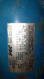
I'm swapping out the 1hp 600v motor that came with my Bridgeport for a 1.5hp 220v single phase motor. I will be reusing the original manual and reversing switch.

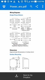
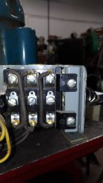
I'm not exactly sure how to hook up the motor to the drum switch correctly. I believe I found the manual for the original style of Cutler Hammer "O" drum switch, but I want to be sure as to which one is the correct diagram before I hook it up to any power.

My main concern is that the motor wiring diagrams wants P1 with L1, but under these diagrams there's no wire for P1, which is part of the thermal reset.

If anyone can point me in the right direction it would be greatly appreciated.
 

Attachments

  • 18051999_10212305215722986_1719210847_n.jpg
    18051999_10212305215722986_1719210847_n.jpg
    58.9 KB · Views: 535
  • 18073156_10212305546131246_612110334_n.jpg
    18073156_10212305546131246_612110334_n.jpg
    30.3 KB · Views: 1,282
  • 18073635_10212305553451429_535594050_n.jpg
    18073635_10212305553451429_535594050_n.jpg
    62.6 KB · Views: 1,004
  • 18110414_10212305215802988_1866789353_n.jpg
    18110414_10212305215802988_1866789353_n.jpg
    31.5 KB · Views: 1,328
  • 18110769_10212305215842989_121414897_n.jpg
    18110769_10212305215842989_121414897_n.jpg
    32.4 KB · Views: 511
Ok, so ignore the diagram on the switch for a minute and consider what you want to do: P1 and L1 need to be connected whenever the motor is on. T5 or T8 need to be connected in their respective positions for either cw or ccw rotation. What the switch does is let you move between off and either of the two configurations.

P1 will connect to the same terminal on both sides of the switch (line doesn't change)

P2 gets capped no switch hookup

T1 and P3 get wirenutted together no switch hookup.

T4 and Line are together on both sides

T2/3 are together on both sides

In one condition, T5 is connected to T4 and Line 2 while T8 is connected to T2/3

In the other, T8 and T5 switch positions.

Now physically look at the "crosswires" on the switch. The ones on the left switch the position of two wires (like maybe T5 and T8?) while the other pole stays the same in either condition (like P1 and Line1) If you just think about it a little it's pretty easy...
 
I don't have time to do a diagram today, but will attach one that shows the switch type you have,
The one you submitted is incorrect it only has 6 terminals and yours is 9 terminals.

This setup is for a different motor at 120V , but with the switch logic and truth table you may be able to sort it out on your own.

SAF Ω

CH Rev Drum SW 1 Ph.jpg

CH Rev Drum SW View1.jpg
 
The P1, P2, and P3 connections are probably thermal cut-out switches. If they're click-type
thermal switches, consider the following:

You are running the machine, and the motor gets too hot. The switch opens. You begin
investigating the issue, and the motor cools. It will then start up - and you many be into the
workings in a bad place when it does.

Ideally thermal cutouts are put in series with contactor coils so that when they operate,
the contactor drops out and will not re-close until you reset it.

One option is to leave the P circuits out of the setup completely, and be aware they're
disabled. Another option is to include them, and be aware if the motor stops in use,
to disconnect the power source before troubleshooting - a wise move in all cases!

If you can get at the internal connections on the motor then this approach works well:

wire.jpg


NOTE: the terminal numbers on the diagram were my own designations during the
wiring job, they're NOT motor terminal numbers.
 
Don't overthink this.

1)Find the leads as labeled on the motor wiring diagram

2) connect the ones that don't need to be connected to the switch as the diagram indicates for the High input voltage (assumed to be 230/240)

3) hook P1 to one end of the switch so that moving the switch to anything besides disconnect connects it to line 1

4) hook t4 to the other end such that in any condition except off it connects to L2

5) connect the third terminal to wires T2 and T3 in either on condition

6) reconfigure the "jumper" wires such that in one instance, T5 hooks to T4 and L2, and T8 hooks to T2 and T3
7) wire the second jumper such that in the alternate condition, T5 hooks to T2/3 and T8 hooks to T4/line2

If the motor quits due to a thermal overload condition, turn the damned thing off and disconnect it from the mains before you work on it.
 
I can't seem to draw this without something being out of place.

The top of the page is how the wires should normally be configured. On the bottom left are the wires which need to be attached to the switch (plus L1 & L2). The lower center is how the switch is configured.

On which numbers would you place wires L1, L2, P1 (T2,T3), T4, T5, T8, and jumpers?

18119745_10212314323190667_170128649_o.jpg
 

Attachments

  • 18136207_10212314307350271_928444091_n.jpg
    18136207_10212314307350271_928444091_n.jpg
    26.7 KB · Views: 407


Back
Top