What's new
What's new

Hitachi WJ200 3 position maintained switch logic wiring?

upthebikes

Cast Iron
Joined
Aug 23, 2007
Location
Great Lakes USA
Hi all - set up my first VFD (hitachi wj200) and it works well so far during testing. I have an older 30mm furnas (now eaton) 3 way rotary selector i’d like to use to control fwd / off / reverse for the spindle. The rotary selector has 1 52baj contact block and 1 52bak contact block mated to a 52sa2cab selector. so I have one NO contact block with two terminals, one NC contact block with two termjnals and a 3 position maintained switch. I think this is the proper set-up.

I wired in a speed pot OK, so I am familiar with the programming and selecting the external logic control from the drive. I am not sure how to physically wire this 3 way switch, as simple as it might be.

Logic input 1 is fwd run ON/OFF, logic input 2 is rev run ON/OFF. I am guessing I have to jumper the switch between 2 terminals of the blocks on the switch? And where would I need to terminate the grounding wire (from the multiconductor shielded cable)?

Thank you in advance. I’ll try to post a picture of the block but recently I know there have been problems with the forum.
 
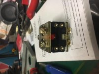
image.jpg photo of the switch blocks. The Photo got rotated, so the switch looks on its side. The NC terminals are on the left and the NO terminals are on the right.
 
Hi all - set up my first VFD (hitachi wj200) and it works well so far during testing. I have an older 30mm furnas (now eaton) 3 way rotary selector i’d like to use to control fwd / off / reverse for the spindle. The rotary selector has 1 52baj contact block and 1 52bak contact block mated to a 52sa2cab selector. so I have one NO contact block with two terminals, one NC contact block with two termjnals and a 3 position maintained switch. I think this is the proper set-up.

I wired in a speed pot OK, so I am familiar with the programming and selecting the external logic control from the drive. I am not sure how to physically wire this 3 way switch, as simple as it might be.

Logic input 1 is fwd run ON/OFF, logic input 2 is rev run ON/OFF. I am guessing I have to jumper the switch between 2 terminals of the blocks on the switch? And where would I need to terminate the grounding wire (from the multiconductor shielded cable)?

Thank you in advance. I’ll try to post a picture of the block but recently I know there have been problems with the forum.

So long as you have a third position usable as a center OFF, (noo I ain't looking up the switch component P/N's) you may be OK.

Logic inputs that do not already have a "pull up" to improve immunity from falsing off noise can be provided with one. One low-wattage resistor, per-each is all. Should be in the manual, most gadgets, noise-immunity / wire length spec as hints if nothing else.

IOW - very, very, unlikely it is not already inbuilt. Were it not, ON/OFF state could be unpredictable, and for both directions. It is not.

Also makes sure your switch is break-before-make AND NOT "transfer", as to "contact form".

If No Joy? Just go and get a different switch. For no more current than this control circuit needs? Not as if they cost real money.
 
That drive has three basic control modes.

1) fwd/off/rev (one switch - center off DPST)

2) on/off and fwd/rev (two switches, both SPST)

3) so-called three wire control, designed to use existing push buttons - one NO and one NC, typically non-reversing.

If you want to use one switch, as mentioned above, it MUST have a center off position, and further needs to have one
closeable contact on either side of the center off.
 
I have wired my Hitachi, with a two position FWD/REV switch,and a push/pull switch ob/off. I've found a three position, too easy to bump on, not a good thing. I've not ever bumped the Pull switch to on.

A couple times I've bumped reverse from fwd. This is because of my wheelchair hitting the switch. Its a rare occurrence.
 
Assume this is a mill, the controls/inputs would different depending on the machine and safety requirements. Normally I do not like rotary or drum "run" switches for safety reasons, I usually recommend 3 wire control which uses two momentary buttons and a 2 way or 3 way (center is off) rotary switch for direction. Momentary buttons are used for run/stop, rotary or any maintained switch selects for reverse run direction. E-Stop interrupts the VFD signal, which is usually P24 connecting to a VFD input (source logic). I have some simple diagrams, but cannot load them here because of the limited file size for downloads.
 
which is usually P24 connecting to a VFD input (source logic).

What would be the advantage of source logic over sink logic here? Reading through both the manual and quick start guide that came with the vfd, it seems like source logic requires an external power supply outside of the vfd? I left the jumper in “sink” position which I think is -24v to the common. This is my first vfd install, a lot to wrap my brain around past the basic start up programming.
 
As mentioned, single switch method can be SINGLE pole double throw, center off. Does not require double pole....

I tend to use the type of logic (sink vs source) that the drive is shipped with. The source supply is, I believe, inherent in the
drive itself. So no extra supply needed in any event.
 
As mentioned, there is a built in 24VDC 100mA power supply in the WJ200 VFD which is used whether you use sink or source logic. No difference, it is just the direction of electrical flow (+/- and -/+). In many of my system designs there are logic diodes which are directional, they can only be used with VFD source logic. I also sometimes use PNP sensors in the VFD input loop which also require source logic, other systems require sink logic. In some cases with the WJ200 if you want to send a JOG signal you need to send both a JOG input command and a separate direction input command. Without a logic diode you would need an extra switch block so when the run command was activated it does not feedback to the JOG input. To change from sink to source, you change one end of the jumper that connects PLC to P24 and flip it to PLC to L, takes about 5 seconds, on many other VFDs there is a switch. Just a matter of design and application. If I could have posted the designs it would have been self evident. If you are just using a rotary switch then it doesn't matter.

When activating an input on the VFD, for sink logic it is a connection from L (GND for analog signals) to the respective input (1-7), source logic it it a connection from P24 to the respective input (1-7).
 
In digging through the manual some more, it looks like I can switch the logic from NO to NC on each individual logic input. so using the 3 way switch I could have FWD RUN to terminal 1 as normal NO, and then switch terminal 2 to NC logic and have REV RUN using the NC block of the switch.
 
Got it running, it was simple once I realized the logic inputs could be switched individually. For anybody out there online looking for a solution, here is a crude sketch of what worked for me. 3 phase motor, wj200 vfd. 18F1DB3B-2E0D-4CE2-B81F-CD621B70CD5F.jpg


Back
Top