What's new
What's new

Hitachi WJ200 VFD, Close loop vector possible?

rbent

Stainless
Joined
Mar 1, 2011
Location
Kansas
I've got a project coming up that I'm looking at using a VFD with closed loop vector control capabilities. I was looking at the Hitachi WJ200 drive, parts of the manual seem like its capable of it, but other parts seem like it needs an expansion card which is a future item.

Anyone have any experience with doing this on the Hitachi drive?

This is my first foray into closed loop vector. It is a really simple project, motor to a screw jack, speed controlled manually via a pot. Forward/reverse push button control with manual knob speed adjust, just dead simple. I would like the power ability at 0 speed given by the closed loop control. I think I could accomplish what I need to with sensorless vector, but would like the 0 speed ability.

I'm looking in the 2-5hp range with a DynaparHS35 encoder on the motor. This is a operate at 75Hz for 4 minutes, then slow down to .5Hz range for a few minutes. It will be a very minimal use item, but the slow speed is crucial to adjustments of the jack.

I've done about a half dozen different VFD's, but never a closed loop vector unit and haven't found a lot out there sub 1.5k$ units that advertise that they are capable.

If you have a suggestion as to a different drive to use that'd also be appreciated if the WJ200 isn't the right one for the job.

Thanks,

Ryan
 
Yeah, I see where the WJ200 literature mentions is, but that's actually incorrect. The Encoder Feedback Board says that it only works with the SJ700 Series drives. The instruction set for the WJ200 doesn't include anything related to Flux Vector Torque Control (which is what you want), but the SJ700 does.

As a general rule, low cost drives, even if they SAY you can add an encoder for feedback, don't necessarily go all the way with that to provide Flux Vector TORQUE Control, it's often just used to improve accuracy on their FV VELOCITY Control and/or positioning.

Thanks for that info on the drive.

So it sounds like the cheaper end of the drives is out. Nice to know that about the Torque control on them as well!

Localish company recommended a Invertek P2 drive but he is looking into that for me.
 
What kind of motor control are you looking for?

We have been using quite a few Nidec M-Series drives (the old Emerson Control-Techniques) with closed loop vector control out of the box and have been very happy.

Unidrive M7�� | AC and Servo Drive from Control Techniques

If you want to do Motion Control in the drive along with a built in PLC it is there with the base model . . . no option cards to buy to connect any number of feedback devices and it will control speed accurately down to 1RPM without difficulty at full torque. We have operated these drives on single phase without any issues also.

For a one-axis systems capable drive, it is hard to beat.

Thanks for the drive recommendation, I will look into those.

Motion control will be a user adjusted speed pot for the drive. This is for replicating an existing process, just at a larger size. Speed will be controlled by a pot while looking at an external feedback system, I'd like to integrate it all into one package but that is a long ways down the road and would be a venture in learning and wouldn't benefit over the open manual control.

I need the near zero speed control for the fine tuning adjustment of the unit, nice to hear on that drive that it won't be a problem.

Is there an estimate as to how long one can run at full power at low/zero speed before thermal kicks in on a TENV motor? I know you can get Baldors with a blower on them, but by the time you get one of those with the encoder I can about buy two of another one. 3Hp, 1750RPM, I've been looking at the Marathon BlackMAX from automationdirect.com

Actual run time on this will be
4 minutes @75Hz
1 minute @ 0-.3Hz
Off for 1min
10 seconds @ .3Hz
Off for 2min
10 seconds @ .3Hz
 
If you have a TENV motor you can run 100% duty cycle at 0.3Hz at full torque 24hrs a day without difficulty. In fact, I would try that drive and a TENV motor without an encoder in RFC mode (I think that is what it's called . . . rotor flux control?) . . . and that might be good enough and if not, then add the encoder and switch to closed loop vector control.

The blackmax motor will work fine as will a bluemax if they make them that small or a baldor Z series TENV
I agree. Try is without the encoder first and see if it gives you what you need, but use a drive that CAN be upgraded if necessary.

Also he's right about the motor too; TENV motors are designed to dissipate heat from the case and the shaft, without the need for forced air movement. The thing to look for is going to be referred to as the "turn down ratio". The Black Max TENV motors will have a turn down ratio of 1000:1 at 40C continuous ambient. That means it is designed to run at 0.06Hz continuously when the air around the motor is 104 degrees F. If you want to use something else, look for those type of specs. As a point of reference, a "standard" motor will probably have a 2:1 turn down ratio at best (when used as Constant Torque), so continuous operation at below 30Hz will likely damage it.
 
If you have a TENV motor you can run 100% duty cycle at 0.3Hz at full torque 24hrs a day without difficulty. In fact, I would try that drive and a TENV motor without an encoder in RFC mode (I think that is what it's called . . . rotor flux control?) . . . and that might be good enough and if not, then add the encoder and switch to closed loop vector control.

The blackmax motor will work fine as will a bluemax if they make them that small or a baldor Z series TENV

Rotor flux control = sensorless vector?
 
Rotor flux control = sensorless vector?

No. Sensorless Vector Control (SVC) is something a little less, the rotor flux is estimated, not calculated, albeit often fairly accurately. But "rotor flux control" is generally referring to an aspect of Field Oriented Control (FOC), more commonly known as "Flux Vector Control" (FVC), a step up in accuracy from SVC. Basically it's fairly easy to implement SVC now even in inexpensive drives because it requires less processing power, often done in a specialized DSP instead of a full blown microprocessor. FVC/FOC has to do a lot more number crunching, usually accomplished with a more powerful multi-core mP or offloaded into a separate math coprocessor. That takes more power and more importantly, cash.
 
The TENV motors have no external fans, but I was under the impression that many have INTERNAL fans that circulate air to help cool the rotor and transfer heat to the case. A lot of heat just goes across the gap, but the gap does not have solid metal all around it on the stator.

As for SVC, the estimation may likely be based on measurements made by the drive in the tuning process, possibly augmented by entered values.

And it is possible to get measurements during operation as well, although that starts to get into the FVC area. We had some consulting from a retired Emerson drive algorithm guru at one point on that, although we ended up not implementing what was initially proposed (and so we sorely missed some sensors he said we did not need). he went through the options for measurements, both in drive automatic tuning, and on-the-fly measurements while operating, to get at information that was not directly accessible..
 
When reading the spec for TENV motors I see turndown, nameplate speed and max speed. Is the turndown related to the nameplate speed or the max speed?

-2¢
 
Thanks for the advise and knowledge on the different forms of vector drive and equipment suggestions. If this project works as planned there will be more of these to do.
 
No. Sensorless Vector Control (SVC) is something a little less, the rotor flux is estimated, not calculated, albeit often fairly accurately. But "rotor flux control" is generally referring to an aspect of Field Oriented Control (FOC), more commonly known as "Flux Vector Control" (FVC), a step up in accuracy from SVC. Basically it's fairly easy to implement SVC now even in inexpensive drives because it requires less processing power, often done in a specialized DSP instead of a full blown microprocessor. FVC/FOC has to do a lot more number crunching, usually accomplished with a more powerful multi-core mP or offloaded into a separate math coprocessor. That takes more power and more importantly, cash.

Today's microcontrollers come in varieties that incorporate floating point instructions and PWM generators. Your comments are at least 10 years behind the times.
 
Today's microcontrollers come in varieties that incorporate floating point instructions and PWM generators. Your comments are at least 10 years behind the times.

rons - while I don't disagree with your statement taken at face value, with all due respect, I think you need to do a little research on the computational HP required to do true FOC (and the consequential benefits in all other aspects of what a systems drive can do).

Nidec/CT M70x -> http://www.emersonindustrial.com/en...chniques/Brochures/unidrive-m700-brochure.pdf

Hitachi -> https://www.hitachi-america.us/supportingdocs/forbus/inverters/Support/SM-E265_WJ200.pdf

The CT drive compared to the Hitachi is similar to comparing an Apple iPhone 8 to the first flip phone
 
No. Sensorless Vector Control (SVC) is something a little less, the rotor flux is estimated, not calculated, albeit often fairly accurately. But "rotor flux control" is generally referring to an aspect of Field Oriented Control (FOC), more commonly known as "Flux Vector Control" (FVC), a step up in accuracy from SVC. Basically it's fairly easy to implement SVC now even in inexpensive drives because it requires less processing power, often done in a specialized DSP instead of a full blown microprocessor. FVC/FOC has to do a lot more number crunching, usually accomplished with a more powerful multi-core mP or offloaded into a separate math coprocessor. That takes more power and more importantly, cash.

Thank you. I always suspected the sensorless vector stuff simply looked at the back emfs on the coils when they were in the
off state. Probably the FVC stuff does so as well, the difference being what they DO with the data once obtained.
 
Thank you. I always suspected the sensorless vector stuff simply looked at the back emfs on the coils when they were in the
off state. Probably the FVC stuff does so as well, the difference being what they DO with the data once obtained.

With an encoder feedback loop, FVC is able to know the exact rotor position (within the resolution of the encoder) at any given moment, so it can update the vector algorithms with that info. In SVC, they are looking at the distortions caused in the current signal by the rotor bars passing by to determine the RELATIVE position of the rotor compared to where it was at the previous mP scan. Better than no feedback by a factor of 10 or more, but not quite as good as FVC by another factor of 10 or more. V/Hz = 1-2% speed accuracy, SVC = 0.1%, FVC = 0.01% or better.

Some drives now also have "Encoderless Flux Vector Control" that takes it a leap further than SVC and does provide a true torque control loop, but is still based on the RELATIVE rotor position from that current feedback loop, just using better current detectors and more mP power. I'm still not convinced of their ability to provide 100% holding torque in a zero speed motor however, as some people claim. ABB made that claim to me once when I was doing crane work at Boeing and insisted on a Torque Proving feature with encoder feedback for the hoists. I told him if he wanted me to accept their encoderless design, I'll lift my 40 ton test weight with their VFD, he can stand under it and I'll release the mechanical brake. He declined.
 
rons - while I don't disagree with your statement taken at face value, with all due respect, I think you need to do a little research on the computational HP required to do true FOC (and the consequential benefits in all other aspects of what a systems drive can do).

Nidec/CT M70x -> http://www.emersonindustrial.com/en...chniques/Brochures/unidrive-m700-brochure.pdf

Hitachi -> https://www.hitachi-america.us/supportingdocs/forbus/inverters/Support/SM-E265_WJ200.pdf

The CT drive compared to the Hitachi is similar to comparing an Apple iPhone 8 to the first flip phone

If you had been in my shoes and have been programming a variety of processors for the last 15 years, going to embedded systems conferences, and reading research papers you would not be making such a statement. Several manufacturers have motor control development kits and libraries that do everything necessary. If a guy is making claims by just reading a few drive brochures then there is a great void, with respect. For example, if you have never heard of Clark & Park then nothing more needs to be typed.
 
If you had been in my shoes and have been programming a variety of processors for the last 15 years, going to embedded systems conferences, and reading research papers you would not be making such a statement. Several manufacturers have motor control development kits and libraries that do everything necessary. If a guy is making claims by just reading a few drive brochures then there is a great void, with respect. For example, if you have never heard of Clark & Park then nothing more needs to be typed.


Actually, it is spelled "Clarke" . . . :) having first investigated it around 1997 when developing FOC algorithms for a Motorola 56xxx series DSP.
Not realizing you have embedded controller programming experience, I gave an answer commensurate with your first response to Jraef. ;)

I no longer write software for doing motor control as was required in the late 80's through early 90's as now drive manufacturers have far better off-the-shelf products than can be economically made from science projects in the lab. My previous employer collaborated with Delta Tau to deploy a number of sinewave commutated high horsepower drives in the late 80's based on the 56000 series DSP with floating point managed by a dual 24bit data bus. Everything written in assembly language requiring the patience of a saint while in the midst of dyne tests with everybody wanting to see results immediately.

The point of my comment above is that the computational HP required to do FOC well ala the CT M70x drive (current loop closure at 3.3kHz / velocity loop closure at 250Hz + managing a real time communications link, motion trajectory generation, and coordination of another axis) . . . and doing all of this well for either an induction motor or a PM motor with or without back EMF suppression, all out of a standard off-the-shelf drive at sub $1000 - is pretty remarkable and requires not only a quality highly capable processor, but also very well engineered code that is elegantly applied.
 
Actually, it is spelled "Clarke" . . . :) having first investigated it around 1997 when developing FOC algorithms for a Motorola 56xxx series DSP.

Not realizing you have embedded controller programming experience, I gave an answer commensurate with your first response to Jraef. ;)

I no longer write software for doing motor control as was required in the late 80's through early 90's as now drive manufacturers have far better off-the-shelf products than can be economically made from science projects in the lab. My previous employer collaborated with Delta Tau to deploy a number of sinewave commutated high horsepower drives in the late 80's based on the 56000 series DSP with floating point managed by a dual 24bit data bus. Everything written in assembly language requiring the patience of a saint while in the midst of dyne tests with everybody wanting to see results immediately.

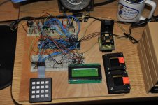
Oh well, spelling. I attended Motorola's 56F8323 DSP class in 2004 or 2005 taught by David Wilson. Also a TI TMS320F2812 DSP class. I bought the demo boards and experimented with them. Those, along with others, depend on a Windows environment, which I don't use any more. Linux and OpenOCD is what I use these days. NXP and ST are my device suppliers today. I went to about a dozen ST-Micro seminars at their site out here in Sunnyvale. All there stuff works with Keil or IAR with limited code size. I brought the boards home and adapted things to work with Linux/OpenOCD and now the code size rule doesn't apply to me anymore. I'm also using FreeRTOS. This was something I worked on last year about this time. I built it to have a set of drivers for display, keyboard, space vector generator, etc. I usually like to start from scratch but using a NXP LPC1769 board (which cost me $1) was hard to resist. The 208 pin sockets on the right side are the next phase probably with a ST-Micro device. Too much metal and paint work this year so it's on hold.


DSC_0888.jpg

DSC_0882.jpg


Back
Top