What's new
What's new

Home built rotery converter questions

Billyboyr66

Aluminum
Joined
May 14, 2016
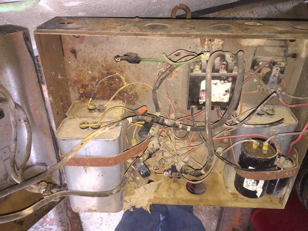
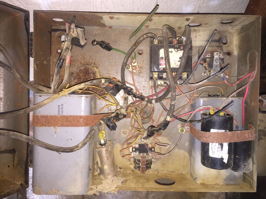
I bought an older round ram j head mill and the guy gave me this rotery converter among some other stuff. It looks like it has been used, but not recently. I have plans to re wire it due to insulation missing on some wires from mice. But before i do i want some more experianced opinions.

Is there anything i should replace, other then wiring? I am going to use some wire distribution blocks vs the eye lets and bolting them together like whom ever built this converter.

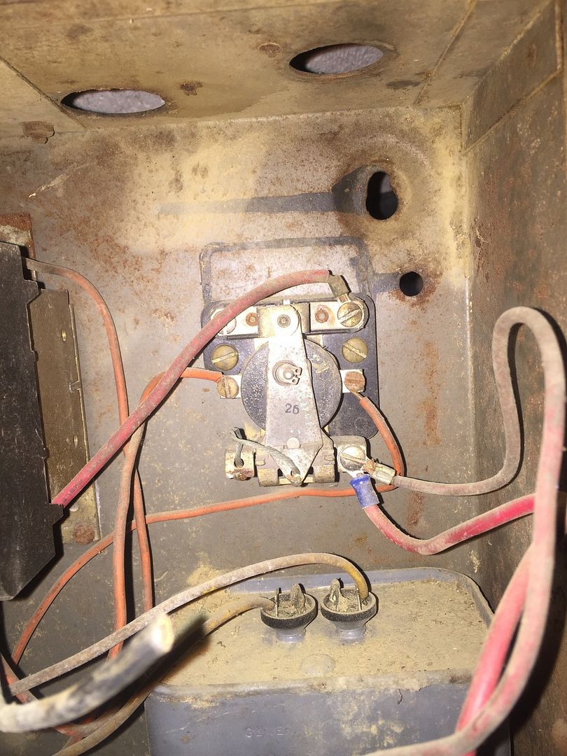
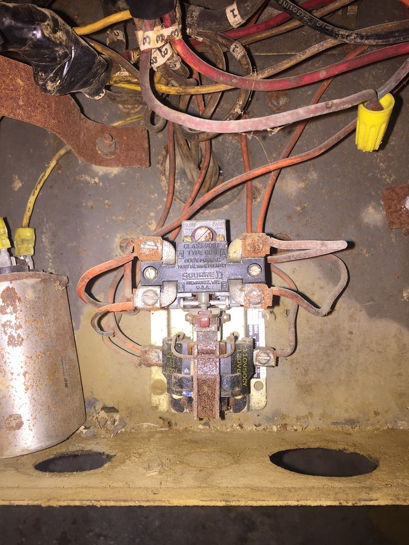
Im no master electrician/or controlls guy so im not sure what some of the items in there are. I would assume That one is contactor, maybe a relay, but as for the rest im not sure. There is no start stop buttons so i assume the past owner controlled it remotely. With that being said id like to do the same but dont know where to connect start/stop controlls to.

Is there a way to check all of the power caps in there to make sure that they are good? Can u ohm them? I know my way around a volt/amp meter and have several.

I know the theory behind the converter, and the basics of how it works but id rather have some other opinions before i run any power to it.


Yes, i just didn't picture the motor. Still trying to figure out exactly what size motor it is. Its big and its heavy. Lol. The id tag is missing from motor though. Its at least a 10 hp motor judging from past experiances with large motors. The controll box i shared pics of was attached to the motor and wired in. i dissconnected it so that i could get it up on my work bench. That motor has to weigh 250 lbs. or more by its self.
 
Repairing a Home Brew RPC

Biilyboy, some pointers on getting a RPC up and running.

First would be to check the motor. Test the windings for continuity. Test for shorts or leakage from each lead to the frame. To determine the HP size look up the Baldor motor frame size chart. Measure the features of the specimen in question and compare to the chart specifications. Once you find a frame size that should put you in the ballpark as to the HP, look in a motor catalog for the frame size to find a comparable HP size.

For the control panel, looks like in it's earlier life it served as a home brew RPC box, later on it became a easy access home to generations of furry critters. Lots of signs of heavy corrosion in there. And therein lies the problem.

The relay and contactor magnetic armatures are heavily corroded and are sure to cause operational issues. The armatures are likely to bind in the rust, and certainly will be noisy with rusty pole faces.If they mechanically bind up trying to operate them, the coils are likely to overheat and burn up in the process.

The large main contactor is to energize the idler motor. The upper right relay is to switch the starting capacitors in and out of the circuit. The lower center relay is a pneumatically operated timer, used to control the start capacitor relay. It is very corroded and not likely to work properly mechanically. The other thing about it is it has a 120V coil, meaning it was connected to the ground to work (bad) or the RPC would require a neutral wire in the feeder. The other relays may have 120V coils as well. Most normal RPC use 240V coils to eliminate the need for a neutral connection, or a illegal connection to the ground wire to operate at 120V.

For the operator control, ON/OFF, there was no remote switch. The switch is the main 2Pole disconnect breaker/switch in the door. No provisions for a remote pilot control, and no circuit protection for the controls is also not a good thing.

For the run and starting caps they can be checked for shorts to the case with an ohm meter, and shorts between terminals. To check the capacitance you need a MFD range on your meter. My guess is the 440V run caps are probably OK. I would be suspect of the black start caps, these are the ones that normally fail after repeated use, and looks to be located as the base for the nest that used to reside there, also could be corroded.

It looks to be a labor of love job, to resuscitate that unit. I'm not saying it can't be done, but it may be easier, safer and cheaper to replace it with a new off the self control panel of a know quantity with a connection diagram. Then you could have a remote operator control, mount the panel on the wall away from the critter farm with all of the entry holes at the floor level. But first you need to determine the motor size and condition in order to select the correct control panel size.

SAF Ω


I have narrowed down the motor to two possibilities. Either one is more then i need so i think thats a good thing. What kind of amperage on the single phase side do i need to feed to this box to run the motor? i have a 30 amp breaker on hand but not sure if its enough. I also have a bunch of #8 wire id like to use to wire it to the panel with. If i remember correctly #8 will cary up to 50 amps. Correct me if im wrong please.
 
To convert 3Φ amperage to 1Φ amperage multiply by 1.732, 10HP 240V 3Φ = 28A FLA

28FLA x 1.732= 48.5FLA 240V 1Φ

#8AWG @ 60 C is rated at 40A, #6AWG is rated at 55A

It may start and run on a 30A Breaker but won't yield full capacity. For a small mill you probably don't need full capacity.

SAF Ω
 
It may work, but I don't recommend it. It needs a heat sink and heat transfer compound to operate at it's rated current. With out that properly accomplished, its rated at less than 10A without it.

Start capacitor surge currents on a 10HP are likely to be way higher than the rating even with the proper heat sink. Get yourself a copy of the cut sheet and read it.

They recommend for phase shifting capacitor currents on starting motors that the voltage rating be twice the voltage being switched. In your case you would need a 480V rating for a 240V motor start circuit.

Your old open relay is probably rated at 30A without any special precautions. In the same footprint size. What is the coil voltage of the relay? It would probably be the easiest of the 3 to clean and reuse provided the coil is the proper voltage and the contacts are still usable.

SAF Ω
 
I went to a junk yard today, and picked up a few things to rebuild converter box. As well as a new looking 5hp three phase motor for $25. Decided to use smaller motor for now.


Once finished building it i temped it in to 240v outlet and to the 5 hp motor. Being half the motor i deleted some of the caps and used smaller box.

At first it would just hum and not spin up so i added second start cap and it then started instantly. I let it fun for a few min. and the two pole main contactor poped like a baloon and it shut down. It did not trip the breaker which is 40 amp. The contactor was rated at 240v and 40 fla. im trying to figure out what happened. Could it be something i wired incorrectly, or im hopeing it was just old and bad part. (Junk yard found part)
 
I took contactor apart and it had just a smudge of black smoke residue in one spot and looks like it came from the coil.
 
I'm all for saving money but why on earth would you trust some old parts found in a junk yard not to explode and burn your shop down ?

You are dealing with dangerous amounts of electricity and risk fire, injury and even death.

Please think this through.

Sent from my SM-N900V using Tapatalk
 
This was an as-built if you will of the original converter box before i took it apart.


I wired the new box just like the old one except i changed the three phase contactor out and used a single phase one and I did not run a third wire on the 240v input side like they did. Im guessing it was a neutral leg but honestly i dont have a clue. It would be the yellow line on my wiring diagram on the input side. They also had the generated leg runing through the main contactor (other yellow line) #3.
 
The yard i go to just cleaned out a space of the royobi plant and they scrapped a bunch of old not used anynore equipment. I caught the tale end of it. Most of the equipment has already been striped and sent to recycler. What was left was mostly automated and pnumatic controlled stuff so not much to choose from.
 
I'm all for saving money but why on earth would you trust some old parts found in a junk yard not to explode and burn your shop down ?

You are dealing with dangerous amounts of electricity and risk fire, injury and even death.

Please think this through.

Sent from my SM-N900V using Tapatalk


1) Relays typically do not "explode". Capacitors can.

2) New parts such as capacitors happily explode if defective (it happens) or if overloaded.

3) Proper electrical enclosures are specifically made to contain the energy inside and not allow the failure to "burn down the shop" if failures occur inside. That's one reason for the short circuit current rating of devices. And for current limiting fuses, grounding, etc.

That said, an old rusty and decrepit relay is not likely to function well or reliably. More because the damage is indicative of bad things happening to it in the past than because rust has some explosive quality. Sounds like the coil failed, possibly due to being the wrong voltage, or just because it had a fault in it, maybe from corrosion due to being wet in the past.

Electricity is powerful and dangerous if mishandled. But it does not lead to Hollywood explosions if reasonably properly handled in sensibly constructed devices. It isn't mysterious, it is just invisible.
 
The drawing is incorrect if it was meant to be to be a representation of the original incarnation. The inputs and outputs connections are reversed. The original incarnation had a two pole breaker in the door that served as the input disconnect and operator control. It does show the capacitor connections off to the side, but lacks the most important element, the idler motor connections.

The original 4 pole contractor was meant to switch the three phase output to the loads,after the start cycle was completed, but was switched to a two pole unit, presumably on the input side. My guess why the coil failed was from sustained high voltage input. Connected to the wild leg for operation, and too much run capacitance causing voltage resonance during is short operation.

Lastly it can't possibly be wired to match the drawing, because it wouldn't start at all, there are no control power taps connected to the input source. The input leads are shown connecting to the power poles of the contactor, with no other tap connections for the control power takeoff. And as I suspected earlier the start timer relay and start capacitor relay have 120V coils and are using the chassis ground as the neutral source.

This is what I meant earlier, by saying: It looks to be a labor of love job, to resuscitate that unit. It looks a lot better than it did, but has a ways to go yet...

SAF Ω
 
1) Relays typically do not "explode". Capacitors can.

2) New parts such as capacitors happily explode if defective (it happens) or if overloaded.

3) Proper electrical enclosures are specifically made to contain the energy inside and not allow the failure to "burn down the shop" if failures occur inside. That's one reason for the short circuit current rating of devices. And for current limiting fuses, grounding, etc.

That said, an old rusty and decrepit relay is not likely to function well or reliably. More because the damage is indicative of bad things happening to it in the past than because rust has some explosive quality. Sounds like the coil failed, possibly due to being the wrong voltage, or just because it had a fault in it, maybe from corrosion due to being wet in the past.

Electricity is powerful and dangerous if mishandled. But it does not lead to Hollywood explosions if reasonably properly handled in sensibly constructed devices. It isn't mysterious, it is just invisible.


Yes even new caps can explode and the enclosure is designed to prevent fire spread. This picture of his parts does not inspire confidence... Rusted caps, contacts and I'll bet money he does not place the cover on the box when he is messing with it..

A new box with quality components is worth a lot less that a night in the hospital or a fire..


Back
Top