What's new
What's new

How do you run the wire from single phase electrical panel to RPC control panel?

kumaichi

Aluminum
Joined
Oct 22, 2014
Location
Charlotte, NC
My previous post was closed due to "meaningless title" so hopefully this title will work?

Onto the questions:

Hi All,

I'm not so electrically inclined so I decided to just buy an American Rotary 30HP phase converter and was wondering if I could get some wiring advice. I have my main electrical panel out in the garage that is installed flush between two studs (it's a finished garage so there's drywall as well). My question is, what is the best way to run the wires inside the wall and then out to the RPC panel? Should I punch a hole through the side of the electrical panel and run it through the stud? Is there some preferred method for bringing the 1ga wire out through the drywall to the RPC panel? The instructions that came with the panel said to use an 80-amp breaker in my single phase box and run 1ga wire from the breaker to the RPC panel. Run 8ga wire from the RPC panel to the idler motor and finally run 4ga wire from the RPC panel to my 3-Phase electrical panel (which will require running the 4ga wire back into the drywall for the 3-phase panel that is installed between two studs).

Thanks in advance for any input,

Craig

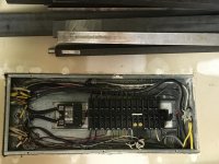
John asked me a question in the previous thread about my main panel and the wire it's connected to. My main electrical panel is a 200amp service that has huge aluminum wire connected to the main service breaker. The sales person over at American Rotary said that with the 80amp breaker in my main service that I'd need to be mindful of what else is pulling a load when I fire up the RPC.
 
A picture is worth a thousand ......

I don't really have anything to take a picture of yet really. The only thing that is in place is my main service that is flush mounted into the wall between two studs. I have my 3-phase panel coming, which is essentially the same as my main flush mounted service and will be installed in the same way, between two studs.

I think I may have found something that will work though for getting the wire through the drywall to the RPC panel, https://s3.amazonaws.com/cesco-content/unilog/Batch6/781747/601440-ProductImageURL.jpg

The link in this post is of a 1/2" LB fitting. 1AWG wire needs a large conduit. I assume you don't need the Neutral wire to power any 125VAC usage in the RPC. You also must run a ground wire with the two 1AWG copper wires. This can be #6 (from NEC memory). You must keep all wires grouped, and 1AWG is not available in NM (non metallic) configuration. NM is also called Romex (which is a trade mark name, but a wire with individual insulated and covered shieth over all the wires.
! inch conduit is a bit on the small size for running 1AWG wires with ground. I would not use anything smaller then 1-1/2" conduit.
You will need to remove drywall from the best access location of a knockout in your circuit breaker panel, going up overhead to some area where you can continue the run to your RPC.
I would use PVC conduit and fittings. They make a "L" fittings with the cover on a side so you can access the wires. These come in left and right configurations.

Given your level of electrical "ignorance" you need to look for youtube videos of many different kinds and see if you can integrate them into doing this wiring task.
Grounding is your safety friend. But seeing how termination is done is important.

A photo of the circuit breaker panel with the cover removed would give others the insight to see the wall and where the knock out is that would be the place to start from.
 
Thanks ignator, I see what you're saying, I'll take some pictures when I get home this evening. Yes, you're correct, the picture I posted is to small, the 1ga wire has an o.d. of almost a 1/2" so yeah, that's not going to work, I'll have to see if they make a 1 1/2" adapter like that. And just so I'm clear, I'll need 3 separate wires like you said, Black, White and Green, they can all be run inside on conduit line correct? I don't need to have a conduit line for each wire?

My intention is to get everything mounted and wire ran, then have an electrician do the final connections, it's just too costly to have them mount everything and run conduit, I can do that sort of thing but I just need to know what "parts" to buy and get installed to try and save some money.

Yeah, I've been tearing up youtube trying to educate myself as much as possible.

Thanks again for your help!
 
Not sure if any of this will be of use in your case as I don't know the layout or setup of your phase convertor and the machine(s) you plan on running with it. But remember that the only wire you need out of your phase convertor is the 3rd or "manufactured leg." Meaning if it serves you better, you can run your two single phase legs right out of your box and into the machine without stopping at the phase convertor. This may be of no use in your situation, but there is no magic being done to your two single phase lines in the convertor. You still have to run the two single phase lines to the convertor, but they do not need to be one in the same as those to the machine. I used this setup when I was in my garage. Main panel in the garage and another in the house basement right next to the well room which was a small concrete block room. I put my phase convertor in the well room and operated it remotely. The only wire I brought back to the garage was a single wire. The manufactured leg. My reason for all this was because I can't stand it, standing there at a machine tool trying to think and have the darn phase convertor humming away in the background. Getting that constant noise out of the shop was a blessing. Ha... wish I could have done the same with the air compressor.

One last thing to always remember too, is do not connect that manufactured leg to any machine transformers, The 3rd leg must go straight to the motor or motor control. Only connect the single phase lines to the transformer. Follow the wires from the main on/off switch on your machine and you'll see that two of them go to a transformer and one does not. Follow that lead. 30 horse... wow... sound like you've got something big and fun going on!
 
Kumaichi: Do NOT use white, this is reserved for a neutral conductor. Use 2 blacks, as there is no phasing to be concerned with (these wires form phase "A" and phase "B"), either green insulated or bare copper can be used for the ground.
As 13engines said, the RPC is generating the 3rd phase, call it phase "C". This you can mark as Red (any color but green, gray, white) on both ends with electrical tape sold for this purpose. Just wrap the exposed insulated part of each end where it's in a connection box.

If there is another large knockout on the top of the existing panel that can be used. You can use a hole saw to make another hole for the conduit connector. This could be ran straight up through the top plate, and there use an elbow or "L" fitting to make a turn. This all depends on your head room if you can live with a long turning radius or need a short 90 that a L fitting gives. The L fitting comes in 3 varieties, so use the one that gives access to the cover plate when installed.
The only issue with drilling a hole is the metal chips need to be controlled. AS well it would be smart to de-energize the panel when doing this. And make sure you don't let the chips get into the guts of any of the breakers by covering them using masking tape and paper over the internals. But a knockout is the ideal way to go. There are knockout punches available, but they are not cheep. And you start with a pilot hole, which the punch uses as a jack screw hole.

Also make sure inside any panel that has a conduit fitting with a threaded end, to have a strain relief bushing. This prevents the sharp edge of the threaded fitting from being able to pierce the wire insulation. It is a code requirement. And it needs to be installed before the wire is pulled in. They have split version of this, but they are costly, and only available from pro supply houses. At any rate the fitting is held in with a lock nut, which is plated steel, and sized for your conduit fitting size. Then this bushing is installed, then you can pull wire.
 
Listen to everything Ignator has to say. He's got the hardware side of all this under his belt. Me on the other hand have lead you only slightly astray. Everything I said earlier is true, though I see one thing is missing. Unless you're running one machine off of one phase convertor in a directly connected daisy chain type system, your 3 phase system should be run out of a separate 3 phase panel. Meaning the wiring to each of your machines should be protected by a three pole breaker. That 3rd wire I spoke of earlier that I brought back to the garage went into a 3 phase panel and became as Ignator suggested, the C leg or Red wire. I'm open to any corrections of this system, but I can't see how you would properly protect a 3 wire system using breakers potentially mounted in two seperate places. A direct connected system on the other hand would be protected by a single 220V_2 wire breaker. My apologies for any confusion.
 
Flush mounted panels in workshops.

Suggestion for dealing with a flush mounted panel in a workshop.

Essentially you need to open the wall up each time you need to add a circuit in your shop. A flush panel looks nice, but is not very practical for modifications in a shop environment. Your equipment will likely change over time, as will their circuit requirements.

Most flexible way is to surface mount all shop equipment, so its able to be modified for changes later. Using an LB fitting (as shown earlier) to get outside the wall cavity is illegal, because a pull point (LB) removable cover is not allowed to be concealed in a wall cavity, and is very hard to get the wire in, the cover will be faceing away from the way you need to pull the wire.

To get an accessible raceway means, to the finished side of the wall cavity use a sheet metal box that is deeper than the wall cavity depth. An 8x8x8 screw cover box will protrude proud of a 4" wall, 4", on a 6" wall 2" of protrusion. Then you can extend outward in all 4 directions, to the downstream equipment.

Use a large conduit between the loadcenter panel and the sheet metal box, bigger than your current needs. It could be up or down or sideways, depending on the actual site conditions.
Conduit in the wall, j box inside and outside the wall, all remaining extensions on the surface.

Keeping the conduit nipple 24" and less, prevents needing to de-rate the multiple conductors in it. Otherwise more than 3 current carrying conductors need de-rating.

Then install any 3Φ on the surface for easy access. When doing the initial layout, think to make a clear conduit path available, for additions and extensions that will be required in the future.

SAF Ω
 
WOW!!! You guys are awesome! I'm posting a picture below of my current single phase load center for the house.

After reading everyone's replies, I think I'm going to change my approach. Please let me know if this is reasonable.

1. Run my 1ga wire through 1 1/2" conduit coming out of my single phase box (2 x black and 1 x green conductors) to my RPC panel or as SAF suggested, get an 8x8x8 box so I can go from inside the wall to surface mount everything using conduit.
2. Run my 4ga wire through a 1 1/2" conduit coming out of my RPC panel (2 x black, 1 x red and 1 x green) to my SURFACE mounted three phase 3 pole (4 wire Non-Breaker) panel (I'm assuming because I'm running an 80amp breaker in my single phase panel, I don't need a "Main Breaker" in my three phase panel).
3. Run my 6ga wire through a 1" conduit coming out of my RPC panel (2 x black, 1 x Red and 1 x green) to my idler motor.

Am I on the straight and narrow now?

Thanks again for all the great education I'm getting from everyone.
 

Attachments

  • BreakerBox.jpg
    BreakerBox.jpg
    91.8 KB · Views: 1,158
  • BreakerBox.jpg
    BreakerBox.jpg
    70.2 KB · Views: 4,875
3. Run my 6ga wire through a 1" conduit coming out of my RPC panel (2 x black, 1 x green) to my idler motor.

You are getting good advice here. I'll just add my 2 cents.

You will need three wires, plus ground, going to the idler motor. That is so you can get the 'magical' third leg to power everything.

In one of the posts above you mentioned getting an electrician to do the final hookup. If that is your plan (and depending upon your knowledge/skill level/experience a very good plan), I might suggest once you are set on the plan (and have it all drawn out) find the electrician at that point. He could hopefully tell you anything you are doing that is wrong, or more important, in violation of local codes. Some localities have funny interpretations of things - areas where there is not necessarily a right or wrong except in the mind of whoever wrote the rules. Thing is you need more than someone who just messes with house wiring - many 'electricians' of that ilk will have their eyes glaze over when you say 3 phase.

Not sure where you work. If a plant, or you have friends who work in an industrial environment, a plant maintenance guy might be perfect. Much of the work you are going to have to do is just mount boxes, run conduit, pull wire. You need to do it neat, pay attention to detail - but it is not rocket science. Making sure the 'magic smoke' does not come out of any of the equipment - now that is the rocket science.


Dale
 
That was a good catch Dale, I added a red wire as well to my "plan" for the idler motor. Unfortunately, I don't work in a shop environment so I don't have access to people in the know. I'm a software engineer, that's one of the reasons why I struggle so with electricity, lol.
 
WOW!!! You guys are awesome! I'm posting a picture below of my current single phase load center for the house.

After reading everyone's replies, I think I'm going to change my approach. Please let me know if this is reasonable.

1. Run my 1ga wire through 1 1/2" conduit coming out of my single phase box (2 x black and 1 x green conductors) to my RPC panel or as SAF suggested, get an 8x8x8 box so I can go from inside the wall to surface mount everything using conduit.
2. Run my 4ga wire through a 1 1/2" conduit coming out of my RPC panel (2 x black, 1 x red and 1 x green) to my SURFACE mounted three phase 3 pole (4 wire Non-Breaker) panel (I'm assuming because I'm running an 80amp breaker in my single phase panel, I don't need a "Main Breaker" in my three phase panel).
3. Run my 6ga wire through a 1" conduit coming out of my RPC panel (2 x black, 1 x Red and 1 x green) to my idler motor.

Am I on the straight and narrow now?

Thanks again for all the great education I'm getting from everyone.


It appears that all the current connections go out the top or bottom of the panel. I do see knockouts near the bottom that go out the rear, is this an exterior wall behind this panel? Could you run PVC gray electrical conduit there, or is this something that would be to objectionable to the aesthetic police? From there you could go underground to where wanted, it's along the path. You would use LB fitting to make a tight bend out the back straight down, or it can be strapped to the building at a fixed height to where the entry box to the RPC would be located. If underground current code is 18" deep, if in conduit then you don't need underground service entrance wire, but direct burial would need that sort of insulation.

It does look like the main power wires come in from the bottom of the panel and reach to the top where the main circuit breaker is.
If the rear path is not wanted, how about a left or right side output. The problem is, you don't know where other wires are until you cut through the drywall. If you are looking to place the conduit on the inside surface of the building as SAF suggests, look for knockouts on the side that are convenient.

The main power run to the RPC is the main task.

As for breaker size, the breaker is designed to protect the wire, not the load. 1AWG depending on insulation temp. and where it's located is nominally good for 200amp (80 degC insulation), 4AWG is good for 125amps, and 6AWG is good for 95amps. So your 80 amp breaker will protect the system.
As for the end motors, you need motor contactors with correctly sized heaters, that will trip if you overload the maximum motor current. Each motor gets its own contactor set for each motors max current. And these are located near the start stop local machine wiring.
 
Here is mine. Shop had its own 200a service. 200a single phase panel on the right, 30hp american rotary converter on the left, 3 phase panel in the middle. Idler below on the floor. I think I have a 125a breaker in the main panel feeding the converter.


Here is mine. Shop had its own 200a service. 200a single phase panel on the right, 30hp american rotary converter on the left, 3 phase panel in the middle. Idler below on the floor. I think I have a 125a breaker in the main panel feeding the converter.


That's EXACTLY what I want, only difference is my single phase panel is in between two studs. Thanks for sharing.
 
I'm a software engineer, that's one of the reasons why I struggle so with electricity, lol.

Won't hold it against you. I'm a retired mechanical engineer who was hired by a large blue company back in 1974. Before I got there the job and department were eliminated so they made me a programmer. Took me 7 years and 3d location before I escaped to what really interested me. Good experience but I really don't want to do 370 assembler or B-52 diagnostic programming any more......

Once you get the 3 phase figured out and up and running you'll be surprised what an 'expert' you will have become.

Dale

Dale


Back
Top