What's new
What's new

Start Capacitor

HarryD

Plastic
Joined
Mar 15, 2005
Location
Wise,VA
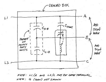
Several months ago (3/20/05)it was recommened that I add 150mfd & 90 mfd capacitors to my rotary phase converter. The 150mfd capacitor was to be added across the leg that contained the start capacitor(s), and the 90 mfd was to be placed across the other leg.
My problem is I am using a Cedarberg, Solid State Phase Converter (Series 1a, Model 1600A) as a "start" (capacitor). This is sealed unit. Is there any way of determining which leg contains the "start" (capacitor)?
 
Dear HarryD,

capacitors do not conduct Direct current, so disconnnecting, both the the input and output of the convertor and using a multi meter, set to ohms, there should be one output wire that appears only to "kick" and then show an open cicuit. Any isolating switches in the convertor should be set to "on".

If all three wires appear to be open cicuit to each other, then it means that the internal conntrol gear of the convertor only connects the output when every thing is OK.

If the above is true, what you will have to do is to work on the fact that a capacitor has an impedance to alternating current. For this test, you will have to measure the phase to phase voltages and note them when the motor is running then measure them again when the motor is isolated, and again note them. The readings that change the LEAST do NOT have the capacitor.

Be careful cos the voltages are strictly lethal
 
With no power supplied and the idler motor in the circuit the resistance L1 - L2 (220v, single phase supply lines) is infinite, i.e., open. The resistance L1 - Mfd (manufacturer phase) and L2 - Mfd is approximately zero, i.e., a dead short.
HarryD
 
Here's a possible schematic diagram for a sealed box static.

Small_Sealed_Static.jpg


Using just a DMM, set for resistance measurements:

1) measuring from terminals L1/A to B you should observe a low resistance slowly increasing to a very large resistance, perhaps infinite (assuming very good capacitors),

2) measuring from terminals L2/C to B you should observe the same behavior, initially, but the resistance measurement should ultimately hold at that which is approximately the equivalent series resistance of the coil within the potential relay (the sealed box within the sealed box).

Now, if you have confidence in your electrical skills, you could perform an additional test, namely applying 240 volts ac, through a series protective resistor, say, a 1,500 ohm, 5 watt resistor of the type usually used to discharge capacitors, alternately to terminals L1/A-B and L2/C-B and observe the behavior of the static.

If you should hear a "click", representing the opening of the contacts within the potential relay, then you've found terminals L2/B and B.

If you don't hear a "click", then you haven't found those terminals.

Once you have correctly identified terminals L1/A, L2/C and B, then you can confidently add the recommended 150 uF/370 vac run cap to L1/A-B and the recommended 90 uF/370 vac run cap to L2/C-B.
 
If you use the terminal designation (from diagram above)L1/A, B, and L2/C I get the following results with the static converter completely isolated. Using a DMM to measure resistance, with the negative (common) probe connected to terminal B and positive probe connected to terminal L1/A I get an open circuit. With the negative probe connected to terminal B and the positive probe connected to terminal L2/C I measure 30K ohms resistance. The meter does not seem to be climbing slowly. If I reverse the probes on terminals L2/C - B, i.e., connect the negative probe to terminal L2/C and the positive probe to B I get an open circuit.
HarryD
 
Let's assume the above diagram is correct.

Use a resistor, about 1,500 ohms, to dischrarge every possible combination of terminals, and then repeat the tests. Repeat the tests with reversal of the DMM leads.

A charged cap will appear to be a high resistance (open circuit) in one direction, but a low resistance in the other direction.

Reversing the DMM leads can cause the cap to discharge and then recharge with the opposite polarity.

A Steveco potential relay I tested just now showed a 7.2 K resistance for the coil alone, so the 30 K you observed could be your potential relay coil, or a simulated potential relay.

Some static converters use a conventional, sensitive relay and an adjustable series resistance to alter the pull-in and drop-out points, instead of a commercial potential relay.


Back
Top