What's new
What's new

Identifying 3 phase motor for RPC project

Deerehauler

Aluminum
Joined
Jan 8, 2017
I am planning to build a rotary phase converter for a 20 HP 3 phase motor that drives a hydraulic pump powering a C-frame press/ironworker.

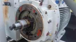
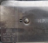
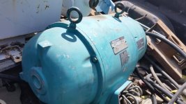
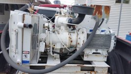
I hope to use the motor pictured on this Ingersoll Rand rotary screw compressor. It was made in 1986 and has been sitting for at least 22 years. It turns over (which surprised me) and I have removed compressor from the motor since this picture was taken. Since this unit was not shedded, any labels have been faded beyond recognition. I included a picture of the nameplate on the motor, which doesn't help me. I am really hoping someone can tell me more about this motor.

The unit was fed with #2 copper and the starter contacts are rated for 150 amps. The wires going into the motor are #10. The schematic for the panel says that is is for motors ranging from 15 to 40hp. The heaters on the starter are labeled FS-87. I hope this motor is 40hp.

I would appreciate anyone's insight regarding the HP and RPM of this motor. Thank you in advance. 20180522_181114.jpg20180522_181051.jpg
 
I am planning to build a rotary phase converter for a 20 HP 3 phase motor that drives a hydraulic pump powering a C-frame press/ironworker.

I hope to use the motor pictured on this Ingersoll Rand rotary screw compressor. It was made in 1986 and has been sitting for at least 22 years. It turns over (which surprised me) and I have removed compressor from the motor since this picture was taken. Since this unit was not shedded, any labels have been faded beyond recognition. I included a picture of the nameplate on the motor, which doesn't help me. I am really hoping someone can tell me more about this motor.

The unit was fed with #2 copper and the starter contacts are rated for 150 amps. The wires going into the motor are #10. The schematic for the panel says that is is for motors ranging from 15 to 40hp. The heaters on the starter are labeled FS-87. I hope this motor is 40hp.

I would appreciate anyone's insight regarding the HP and RPM of this motor. Thank you in advance. View attachment 229113View attachment 229114

Most large machines have a nameplate that state the horsepower of the largest motor. This is often tucked inside the electrical panel as well. Have you found anything like that?

If not, identify the type of motor, whether it is an open frame or TEFC. It looks TEFC from the picture, but I can't tell for sure.

Is there anything stating the flow rate of the compressor? If you know the flow and pressure you can calculate horsepower.

Alternatively, contactors usually have a table on the top or side of them that tells you what horepower it can drive at what voltage.

If all else fails, take some measurements to determine your frame size of the motor. This will give you a range of horsepower the motor could be.

The nameplate wiring diagram shows this is a dual voltage motor, so most likely 230/460. As far as RPM goes you would need to either run it or take off the rear casting that supports the bearings and look at the windings, as far as I know.
 
Shaft height is a place to start on nailing frame size

8" high gets you a 324 used on 40HP 1800 RPM as of '64 rerate, while 9" gets you a 364 used on 40HP 1200 RPM as of the '64 rerate
 
Thanks gents for your replies. I believe this is a drip-proof motor, since there are holes in both ends. The wiring diagram in the panel stated 'for 15-40 hp motor'. I took a picture of the starter, perhaps that will help. I measured 6 1/4" from the base to the centerline of the shaft. The finned part of the motor is 11 1/4" and the overall length is 19" excluding the shaft.

Since I want to use this motor as an idler, the RPM is not critical other than I intend to get this rolling with a pony motor. I am not familiar with screw compressors but I assume they would run in the 3000-4000 rpm range.

right side up.jpg
 
6.25" shaft height is a 254T or 256T frame size. That puts you in a 15-25HP range for an open drip-proof fan cooled C Face motor, depending on RPM rating.

The starter looks to be a Westinghouse type re-branded. FS-87 are not a good part # for Westinghouse, but an FH87 is rated for 73-84A depending on starter type Size 3 or 4.

Better photos of the motor tag and starter may help. Need to see the entire thing. Not just a partial tag.

# 2AWG wire is rated for 95A @ 60C or 115A @ 75C. It appears that the unit was configured for low voltage, should be able to tell by how the motor leads are connected.

3Φ Motor NEC Full Load Current Chart.jpg

SAF Ω
 
6.25" shaft height is a 254T or 256T frame size. That puts you in a 15-25HP range for an open drip-proof fan cooled C Face motor, depending on RPM rating.

The starter looks to be a Westinghouse type re-branded. FS-87 are not a good part # for Westinghouse, but an FH87 is rated for 73-84A depending on starter type Size 3 or 4.

Better photos of the motor tag and starter may help. Need to see the entire thing. Not just a partial tag.

# 2AWG wire is rated for 95A @ 60C or 115A @ 75C. It appears that the unit was configured for low voltage, should be able to tell by how the motor leads are connected.

View attachment 229198

SAF Ω

Any idea what service factor compressors usually use? That extra 15% capacity can be useful in RPCs
 
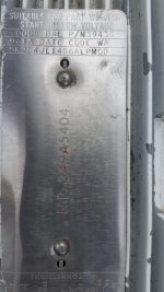
I did some more checking and the motor is wired for low voltage (3,5,9:2.4.8:1.6.7). The motor data plate is sorely lacking. I have not removed the motor from the frame, but I cannot imagine a full data plate being on the bottom of the motor. The bolts mounting the compressor adapter to the motor are 1/2" and are on a 7 1/4" circle. The housing pilot is 8 1/2"

I took some better pics of the contactor. Good call on the heaters, they are FH87. I took some more pictures, I hope they help. Thanks to everyone for your help!
20180523_184307.jpg20180523_183616.jpg20180523_184132.jpg20180523_183629.jpg20180523_183853.jpg

Looking closely at the motor plate it shows the motor wound Delta. Is this a problem?
 
I did some more inspection and checking and removed the end caps from the motor. The windings all look good and check good with the megger. I blew out all the dirt. The stator is 6 1/8" in diameter and the flat part of the stator (where the rotor runs) is 5 1/4". It has ball bearings on both ends and they were VERY well greased (almost too much).
 
That one was a smooth runner (well balenced).
I sent you a PM Deerehauler

I never did get to see/hear this run. It previously belonged to a long defunct boat manufacturing company in Oberlin, Kansas. My previous employer, a John Deere dealer, bought it to use for either a shop compressor or to blow off combines before they came into the shop. It would not build enough air pressure to use in the shop and the air got VERY hot when used to blow off equipment. Added into the problems was the cost of trenching in a long run of VERY heavy wire so this could be operated far from the shop and storage buildings. They put it on a pallet and set it back in a corner of the lot. I worked there 21 years and it stayed in same place until I loaded it up a couple days ago.
 
From the heater size it appears to be a 30HP 230V, in a smaller diameter and longer than normal frame size, likely a 3600RPM, a special.

The delta winding is not the best choice for a RPC build, as compared to a wye wound unit.
Take a look at the connection tag, one of the windings will be receiving half voltage with just two phases powering it. As it is wound for a part winding start.

Hydraulic pumps are a difficult load for a RPC, and you should be sizing the RPC at least 2X for reliable use. Combine that with one winding receiving half voltage, and I would say that it's not a good fit for your purpose.

dual volt delta.jpg

SAF Ω
 
From the heater size it appears to be a 30HP 230V, in a smaller diameter and longer than normal frame size, likely a 3600RPM, a special.

The delta winding is not the best choice for a RPC build, as compared to a wye wound unit.
Take a look at the connection tag, one of the windings will be receiving half voltage with just two phases powering it. As it is wound for a part winding start.

Hydraulic pumps are a difficult load for a RPC, and you should be sizing the RPC at least 2X for reliable use. Combine that with one winding receiving half voltage, and I would say that it's not a good fit for your purpose.

View attachment 229227

SAF Ω

It was my understanding that with RPCs you have one driving winding and two generating windings. After all you are generating two phases of current, even if it only comes from one additional leg. I wish I had some small 3 phase motors or I would cut out the winding that you say is the only one generating and see what the other one is doing.

But in any case under operating conditions there is no winding at half voltage that I can see. Looking at the schematic I can see the voltage divider formed by the windings, and how it could appear to be two windings in series and thus receiving half voltage, but due to the induction from the driving winding to the rotor and back to the generating windings it behaves far, far differently than just two uncoupled inductors in series.

But of course I could be wrong and please correct me if that is the case.


Also, huge red flag on that motor. Whoever decided to grease the ever loving shit out of those bearings paid no though to where the extra grease was going. Be sure to check that it hasn't gotten on the windings. I doubt they used proper grease for electric motors. I would hope it's made to purge safely, but that's a lot of grease.

After taking the picture I cleaned most of the grease residue off the windings. I used some brake cleaner after I blew most of the crusty dry stuff off. The grease did not seem to have worked into the windings themselves, just coated the outside. The shaft end was not nearly as bad.

The press came with a 20 hp motor and close coupled hydraulic gear pump. The pump is not usable, and I intend to replace it with a vane-style pump. I wanted to use a vane pump because it will not pump any oil below 600 RPM and I thought that might make the 20HP motor a little easier to start.

I have been reading the forum about adding another idler to the circuit, which if I understand correctly would increase my starting power. I see the sequence as: start pony motor and get former compressor motor up to speed. Power up compressor motor, then power up second idler motor. After it reaches speed, then power up hydraulic pump motor. As long as the second idler motor is less HP than the compressor motor, it should start with little effort, right?

So long as it has no inertial load I would be comfortable starting an equally sized motor as the idler. My 10hp RPC would be able to start a 30hp motor if it were on a bigger breaker. (Trips out at after a few seconds but that has very large rollers and a sanding belt it has to spin up too).

One consideration is that for part of the motor's rotation it uses one winding to spin the motor and setup and eddy current in the rotor. The rest of the rotation it acts as a generator and extracts mechanical (spinning) energy of the rotor through two windings. So if you are pulling the FLA of your idler on the input, the generating windings are well below FLA because the current is split between the two. For this reason I would recommend getting something like a 5hp pony rated at the same rpm and leave it running constantly. This will give a little bit more output power through the generating windings without maxing out the input windings any further. You will of course have to clamp an ammeter on each motor winding to verify you are in safe operating limits (capacitors also add reactive current which can blow motors. Reactive current is half of my idler's FLA on my RPC, but goes down with load) and also verify you aren't over the FLA of your pony motor. If you can get a 1.15 service factor on the pony to give you a little more oomph. You can bolster your output with capacitors if your motors are insufficient but bigger idlers make much better three phase than capacitors.

If the pump motor is 3600 rpm having a pump that doesn't operate until 600 rpm will help a little but I think you will see a big advantage by plumbing a valve across the inlet and outlet of the pump for startup to make the shortest, lowest reistance and inertia circuit you can get. Then close the valve once you are at operating speed.
 
The hydraulic pump motor is rated at 1800. I included some pics of the motor and data plate.

I am now a little confused. I was planning to use a 3/4hp single phase motor to spin the compressor(idler) motor up to speed before applying power to the compressor motor. Once the compressor motor is up to speed and generating the third leg, I would then start the pump motor.

If I understand you correctly, I could use a 5 hp 3 phase pony motor to initially generate a third leg, once it is up to speed, I could then start the compressor(idler) motor, and once it is running to speed, then I would start the hydraulic pump motor? There would be no mechanical coupling between the 5hp pony motor and the 30hp compressor motor?

20180524_120254.jpg20180524_120314_1527182422846.jpg
 
The hydraulic pump motor is rated at 1800. I included some pics of the motor and data plate.

I am now a little confused. I was planning to use a 3/4hp single phase motor to spin the compressor(idler) motor up to speed before applying power to the compressor motor. Once the compressor motor is up to speed and generating the third leg, I would then start the pump motor.

If I understand you correctly, I could use a 5 hp 3 phase pony motor to initially generate a third leg, once it is up to speed, I could then start the compressor(idler) motor, and once it is running to speed, then I would start the hydraulic pump motor? There would be no mechanical coupling between the 5hp pony motor and the 30hp compressor motor?

View attachment 229256View attachment 229257

The pony motor would be a single phase motor mechanically coupled to the idler motor. My point is that if you leave the pony motor on it can add to the horsepower capacity of the idler. So if you have a 30 horse idler and a 5 horse single phase pony coupled to it you have essentially a 35 horse idler. This works because the windings in the idler that are pulling power from the line are more stressed than the windings the third leg comes from, so you can add a bit of mechanical power to get more electrical power out than you could otherwise put in through electrical means only.

You can use a small 3 phase motor to "pony up" a larger motor electrically (no mechanical link), but it may start a little rough. You can easily start 10hp with capacitors, and I think a 10hp motor could start a 20hp idler unloaded, which may be easier than mechanically mounting a single phase pony motor.
 
Ok, now I understand.... My next mission will be to figure out how fast the compressor(idler)motor is designed to turn. I can 'borrrow' some low voltage 3 phase to check this out.

In the event that the compressor motor (being kind of an oddball) turns an uncommon RPM, would it be better to have the single phase pony slightly overdrive the idler or vice versa. I could see benefits in either case. Which would be better?

It won't turn at an oddball RPM. It will have a synchronous speed (unloaded speed) of 3600 rpm or 1800 rpm. Speed at full load will be somewhere between 1720-1760 or 3420-3480 RPM. That little bit of variance will determine how much power your pony motor contributes when the idler motor is fully loaded. The slower the idler rating the less likely it will contribute more power than it can continuously handle. Motor speeds must match within ~100 rpm.

I should clarify that you only need a large pony motor if your idler motors are insufficient, and it could be difficult to "balance" how much power the pony contributes. Your original idea of a 3/4hp pony should work fine and be easier to implement, assuming you have the idler horsepower requirements taken care of.

Disclaimer: I haven't hooked up a pony motor this way. It's how I plan to make my 30HP capacity (60HP idlers) RPC, but I have not finished it yet.
 
For the differences on using a wye or delta motor for a RPC idler. Draw yourself a sketch of the winding patterns.

With a wye, your two line terminals power two of the phase windings (parallel wye, for low voltage). Using the third phase for the manufactured line.

With a delta, your two line terminals power a single phase winding, using the remaining two windings to generate the manufactured line.

It's not that a delta won't work, but you can only input so much in a single winding. Two is better.

I see the part winding start capability, your idler has, is an even further detriment. Make a sketch, like the connection diagram. The two line terminals powers up, two windings in the corners of the delta with full voltage, but the opposite corner is set up as a voltage divider, two windings sharing line voltage.

In regards to a hydraulic pump load @ 20HP 240V off of a RPC, you might want to have a look here:
http://www.practicalmachinist.com/vb/transformers-phase-converters-and-vfd/phase-converter-lacks-power-run-shear-309973/?highlight=hydraulic+pump+phase+converter

And this is with a quality wye type RPC.

SAF Ω

I didn't understand the part winding start capability. So this motor could be wired to start on two of three phases? I am really learning a lot with this discussion. I used to work on electric center pivot irrigation systems, but those are pretty simple for the most part. The motors either worked or they didn't.

It would not take a huge effort to put a dump valve on the output of the pump, which combined with the characteristics of the no-load starting of the vane pump, should make the pump motor as easy to start as possible. I read the link about the guy having trouble with the hydraulic shear. I have a TIG welder that will pull 103 amps out of the wall. I could test the voltage drop of my shop power when the welder is running wide open.

I had an old Hobart Cybertig and the control gater was getting weak. It was supposed to be calibrated for maximum welding output of 305 amps by shorting the leads together and mashing the pedal all the way down. The amp meter on the front of the panel would go to 450 amps and with the gater malfunctioning the amp meter would peg out. That would dim the lights in the shop a little...


Back
Top