cinematechnic
Cast Iron
- Joined
- Apr 11, 2005
- Location
- Walnut Creek, CA
I'm planning on adding a VFD to my lathe, which has a 380V 50Hz motor and built-in transformer. My power is 208V 60Hz 3ØY, the lathe's internal transformer will boost that to 380V (or higher), that would input to a 460V VFD.
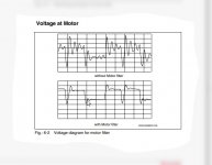
My questions: Is there an advantage to running a line reactor / load reactor on the output side of the VFD? Would it be a good idea to do so when running a VFD with an older non-inverter duty motor? Will this protect the windings?
The motor is a high quality (Swiss made) motor, but is non inverter duty. It is a 2 speed 8 pole/2 pole motor. Please refer to my previous thread for details on the motor.
The lathe was made in 1982. I had the motor serviced by a motor rebuilder in 2008, and was told the motor was fine (I assume he tested the windings). I have no way of knowing what the insulation class is on the motor windings. But its not likely to be higher than 600V is it? I'm a bit concerned that if I'm running a 400V VFD and my windings are 600V insulation, that's only a 200V margin of safety for the voltage transients, etc.
Also: I'm assuming an AC reactor on the input side would be superfluous because there will be a big transformer on the input side of the VFD.