kitno455
Titanium
- Joined
- Jul 9, 2010
- Location
- Virginia, USA
Hello all- first post here, but I've been lurking for a couple weeks. I've learned a great deal already from reading old posts, thanks for that!
Anyway- some background:
1. I've just gotten my first mill/drill, an original RF-30, 3 phase, 240v, 2 speed motor: 2hp, 1640 rpm, 6.3 amp, 4pole or 1hp, 820rpm, 6.4 amp, 8 pole.
2. I have purchased a 2hp Teco EV Single phase input VFD.
3. I have tested the VFD on the mill with some temporary wiring, and it works well, other than some vibration at certain speeds. This may have been caused by broken connections in the motor junction box.
4. All of the original wiring and controls were 'suspect' due to prior modifications and damage. They have all been removed.
Now, my questions:
1. I wish to wire the motor for higher speed, but the label in the motor junction box leaves something to be desired (particularly clarity). It appears that I should connect 1,2,3 together, and connect 4,5,6 each to one of the inputs from the vfd. Does this seem accurate?
2. I intend to mount the vfd on the wall behind the mill, as it seems too open to be near the swarf, and run a set of low voltage controls on the head. I have NO muscle memory as this is my first mill, so I wonder what is the optimal set of controls? Three Fwd, Stop, Rev buttons, plus a speed control pot, or a drum switch plus the pot, or Stop/Run buttons with a direction switch, etc, etc...
3. I want an E-stop that kills everything, including the VFD. I would prefer if it had multiple button locations. Is this accomplished with a contactor on the VFD input?
4. The VFD continues to run when the power is disconnected. Can I make use of this fact to tell the VFD to brake the spindle at maximum rate, using external resistor if one is fitted? ( I want the E-stop to actually mean something )
Thanks for any help or pointers you can provide.
allan
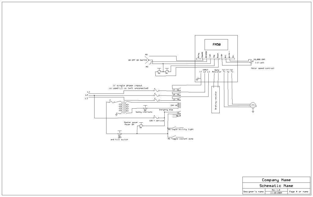
") I would prefer to do both, have the vfd engage the brake for as long as it's caps last, while pulling the mains out at the same time.
I would prefer to do both, have the vfd engage the brake for as long as it's caps last, while pulling the mains out at the same time.