What's new
What's new

Multi-choice power Question. 1ph 240VAC supply...

MihiT

Aluminum
Joined
Mar 22, 2018
Hi,
I'm mainly looking to pick brains here. I'll try and be as clear as possible but pretty much just brainstorming at the mo...

My available power supply is ~240VAC Line-Neutral (1ph).
I have a number of 3ph motors I'd like to make use of, ranging from 380, 400, 420, 440 etc. One of these is dual wound(?) for "220/240 - 380/420"

I could potentially use it as an RPC, however I'm guessing that putting 240 in will not generate 440 out?
OR is it likely that it would be wired in such a way that If I carried the the 240 legs through, the generated leg would also be at 240, giving me 480 line-line? How can I test this (without putting power to it and letting the smoke out(‽))
Follow up question - would it be safe to swap legs on this output to provide 3ph reverse on driven motors?

The second question I have concerns a 3ph transformers - I was looking at a 400-240 reducing 3ph transformer.
Could this be wired "backwards" and with the phases/coils split, ie 240 -> 480, then wire that to the next coil for 480 -> 960 and to the next 960 -> 1920?

Thirdly, to kind-of combine the above, if I run my dual-wound at 240 as an RPC to get 3ph 240, then "backwards" through the 3ph transformer to go from 3ph 240 to 3ph 440 and then can run all the other motors from the transformer output.

And finally, am I fairly safe in provididng ~480VAC to a 380 rated motor? surely more voltage = less current = less heat = more torque(?)

I should mention I'm in New Zealand, and I'm not on speaking terms with OSH, so I'm looking for a working(safe) solution, if not entirely code compliant.

Cheers for your time.
 
480V would be fine for a 380V 50 Hz motor IF the 480V WERE 60Hz.. Otherwise, it is a fair bit high, and may end up saturating the iron and drawing way too much current. Not recommended. it is 20% high for nominal, and could go another 10% more, 10% is the usual limit overall.

The transformer should work backwards. A few have compensation built in, and may provide a lower voltage than expected when run backwards.
 
Cheers. Domestic power here is all 50cyc/Hz.
Yes I expected it would be a rather lossy system, even if everything is 98% efficiency that's still 6% loss before loading the motors. :/
 
Hi Mihit,
Your solution is very simple. Use a single phase transformer 240v to 415v, then power a suitable 415v R.P.C. idle motor that will give you a 415v 3 phase output. If you don't have a transformer already and want to modify one yourself you get a suitably sized old 415 volt choke welder and the rest is easy and not much money.

Jim

Simple? Where's the fun in that? :P

Thanks for the suggestion. I'd need to look into that welder thing a bit more. (or if you can elobarate)
They're not very common here, most in the kind of size are 50-60VDC output (240VAC in.) Even the 240-440 transformers don't go for sale often.
 
Simple? Where's the fun in that? :P

Thanks for the suggestion. I'd need to look into that welder thing a bit more. (or if you can elobarate)
They're not very common here, most in the kind of size are 50-60VDC output (240VAC in.) Even the 240-440 transformers don't go for sale often.

Look for a dual voltage arc welder - I'm using an old Oxford oil-cooled as 240-415 autotransformer, it's rated 9 KVA continuous, 11 peak (220A welding output) and if it's anything like my other Oxford oil-cooled it'll run at full whack all day and barely get warm.

You won't need the low-voltage/high-current winding, just feed 240 into the neutral and 240 connections, take 415 from the neutral and 415 - Robert's one's parent's sibling.

Dave H. (the other one)
 
Hi MiHit,
To run 415v 3 phase motors from 240v single phase is Very Simple. If you have a duel voltage 415v single phase welder using the primary winding connected as a autotransformer is Very Simple. The down side is these welders are only made with output up to about 280 Amps so this limits the H.P. of motors you can run and also when you connect your 240v this may be up or down and the primary coil may have more or less turns so the output voltage might be up or down.

So, if you don't have a duel voltage welder you find a 415v sliding Choke welder, remove the secondary windings and all it's winding mechanism, now you have a very large window. Suitably insulate the core and start winding on building wire of suitable size.
You can remove some of the primary Turns checking with an Amp meter till your reading about 2 amps on primary, that should give you about 1.5 volts per turn so probably about 100 turns, just keep testing voltage till you get what you want. Like I said simple.

Now you don't have a welder. My first transformer converter I built and am still using daily. I used from and old 50 H.P. motor the laminated silicon steel stack. I wound 3 x 2.5mm squared in parallel because I found a large qty free and I run a 7.5 H.P. without any trouble. This method is simple but a lot of work with rewarding results. I now recommend to use an old welder because of it's large laminated iron core mass, utilise some of the existing windings and it has a metal enclosure.

You have not said how much power you want to put through this R.P.C.
I think you would have in NZ the C.I.G. Easywelder, 140amps, 240 volts, if you only wanted to run, say, 3 or 4 HP motors you could experiment with one of these, leave primary the same, remover secondaries and wind in the new secondary and connect as autotransformer.

You could view some of my forum posts on this matter.


And as for code in NZ you use the same standard as we do "Australian and New Zealand AS 3000" for the installation, so you would probably be RCD protected which would be very suitable for this application. If your C.B is tripping on in rush current, replace your existing "C" type with a "D" type, it will hang on a bit longer for start up.

Jim
 
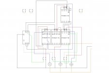
Phase convertor control plane.JPGView attachment 224869

An interlocked contactor setup I came up with - from the left, control relay, output contactor,start contactor, mains in contactor, up above the motor contactor (overload not shown).
Push-buttons and lamps follow the same - output, start, mains.
The flying leads on the right are (top to bottom) coil voltage supply, coil return via some other switchery (tripped by e.g. input MCB, output MCB, output 3-phase RCD, motor overload normally-closed switches all in series), and lamp return.

I haven't incorporated the RPC mains / 3-phase wiring, as it'd get too busy and this is just the "control plane"!

The interlocking (each is fed from the previous coil's voltage) means it only comes up and works if you push the buttons in sequence, mains - start - output, to give your supply breaker an easy time :)

Your implementation may differ, this is just what's worked for me, and works pretty well.

It does require holding the start button until the motor spins up to speed though - such a hardship!

Dave H. (the other one)
 
Last edited:
Hi Dave.
It would be easy to connect a small normally closed relay coil to the generated phase on the idler motor, to disconnect the start caps when motor gets up to speed. I just use any small relay and just put a resistor in the curcuit so when the generated voltage reaches about 80% it energizes coil and points open and start caps disconnect.

Jim
 
Awesome stuff guys. Thanks all. The autotransformer is sounding like a good idea, when I can find one.

Rather than start a new thread, I'll drop this here.
attachment.php


This is the 240/440 motor.
Now I would have thought it was running on 440v 3ph originally, (Red White Blue wires connected ABC2) but I've hooked it into A2-C2 (line-neutral 240VAC) and rope-started it and it runs alright, generating about 201V on B2. I'll add a 40µf A2-B2 to bring it up some.

I did have a moment, when I first wired it, B2-C2 with bar links, as it suggests on the plate. It tripped the CB, and when I measured it (afterwards:nutter:) it came up dead-short.

I'm away from the thing at the moment, but I'll post up the ohm measurements between all terminals if that's of any relevance or would give any clues.

Obviously I'm no sparky, so if one of you could perhaps translate it into normal-speak that would be good.
 
Hi MihiT,
Anything I have said you don't understand, Just let me know and I will try harder. If you post a clear readable picture of the makers rating plate on the motor I will be able to see what you have. Now I am confused.You said earlier you had motors with voltages 380v, 400v, 420v & 440v, so you should be trying to get a 415v output so if you connect your 240v/480v motor to operate from 240v you can only output 240v.
You need to transform 240v single phase into 415v single phase and connect that to a 415v idler motor and then you will have 415v 3phase.
Anyway what HP 3phase motors do you want to run, are any of them hard starting, I mean against a load like an Air compressor or a lathe operating in a high gear.

Jim

Yes I get that, and fairly well have my head around the autotransformer too. cheers.

I kind of went off on my own tangent, at this point I'm happy to have THIS motor spinning, even though it's not doing the higher voltage or RPC. It may end up that I just run a line shaft off this and be it done. It was rated to draw ~8A and worked out to ~1900kW. however running it as above the clamp meter showed only 1.4A drawn on hot wire, even when I tried braking the shaft, so I'm scratching my head a bit there.

The 3ph motor collection is a pile of small 1-3hp. I had a 5 which was going to be my RPC. Then I got sidetracked.


Back
Top