What's new
What's new

Myford Lathe won't start - Inverter issue?

Mouth

Plastic
Joined
Oct 12, 2017
Location
Nottingham
Hi all, I am VERY new to woodworking, I bought a used Myford lathe which was working just fine and I managed to turn my first bowl, towards the end of this the lathe would periodically not start. Then i've gone on to my next attempt and the lathe will no longer start.

When the direction is selected and the start button pushed, the motor moves slightly (10 degrees or so rotation) and makes a noise then stops. This is just repeatable by switching off and on again. Everything turns freely on both directions by hand.

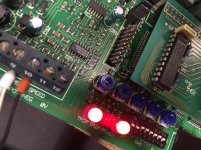
The unit is driven from UK mains single phase voltage 240VAC into an inverter for 3 phase. The inverter unit itself is a Jaguar Cub VCD55 UK and has 2 LED indicators which had no label, so I opened the unit to investigate further/look for anything physically obvious and to check if there were labels on the LEDs inside. When first plugged in the LED labeled POWER illuminates and when the start button is pressed one of the 2 LEDs labelled TRIP illuminates. I don't have a manual for this unit and cannot find one online so i'm not sure the cause of the trip. All wiring checked out OK for connections and continuity.

Can anyone point me in the correct direction for further fault finding so that I can get it up and running again please!
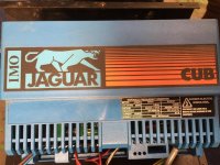
IMG_7124.jpgIMG_7130.jpgIMG_7116.jpgIMG_7102.jpgIMG_7073.jpg
 
Well, first off, here is your manual for the VFD.

https://inverterdrive.com/file/IMO-Jaguar-Cub-Manual

It's very old, probably close to 15 years old, and if it was sitting unused for a long period of time, it's likely that you have blown the capacitors if you did not perform a "capacitor re-forming procedure" before energizing it. It will not be worth fixing, even if it can be fixed. Also, I can't read the motor nameplate FLA, but it appears to be 3. something, and the VFD is rated for 3.0A output. So that might be a bit under sized if you ask me.

A new VFD from a better reputable supplier that sells product here in the US would likely cost less than messing with this dinosaur. IMO got out of the VFD business in this country maybe 10+ years ago and even when they sold them here, they never imported the Jaguar product line, they brand labeled other products like the Teco drives for a while. So Teco, Hitachi, any brand with a US based sales and support channel would be fine for this. Just stay away from the super cheap ones being sold on FleaBay and Amazon coming from China with no name on them, or some odd name like Huanyang. Those are garbage and not worth their price.
 
The two lights presumably have different meanings, so you really need a manual to know what the indication means.

However, you CAn do some testing.

First thing... disconnect from power, and let sit 5 minutes to get the voltage to come down. Then find the wires that go to the motor. With tape and a pen, label where each wire goes, so they can be put back. Disconnect all wires that go to the motor, at the inverter, making sure they are away from connections, parts, etc.

Now reconnect power, and try the start button.

If you STILL get a "trip" indication, there is a very good chance that the inverter is bad.

If there is NO trip indication with the wires disconnected, then the problem is likely to be in the motor or the wires, and you need to find it. Usually that will be wires touching each other, or something else metallic that is earthes. Possibly just one "escaped" strand of multi-strand wire, which is easy to miss seeing.

The rating of the inverter is close to the motor rating, but that should not cause the problem you describe, so long as the motor is free to turn.

That manual has unit pics that do not look like the unit the OP has. Might not apply, his may be an older model.
 
If I disconnect the 3 wires from the inverter to the motor at the inverter end then power up and press the start button the other TRIP LED illuminates. The voltage across the 3 output terminals in any sequence is zero, from one of the terminals to earth measures around 115VAC.

The manual doesn't seem to relate to the model I have with the lathe, I think its probably older than that! I found reference online to that series of inverters being from 1989...
 
Thanks for the link,I have emailed them to see if they have a manual or schematic etc. Worst case, it looks like i'll need to buy a replacement, but i'd rather have a go at finding dodgy components first, the problem is that there doesn't seem to be much online in the way of common flaws with this model. There is a large capacitor on the circuit board which measures the correct capacitance and charges/discharges OK. Nothing looks burnt out and short of actually removing components to test them i'd be at a loss as to how to figure out if somethings broken.
 
One way is reasonably easy if you have a DMM which has both a regular resistance range, and a range for checking diodes.

Disconnect it from motor and line. Let it sit and self-discharge for maybe 30 min.

Now take the cover off, and measure resistance with the DMM on regular resistance, between the motor terminals and the + bus, do same to the - bus (+ and - terminals on the capacitor should be good). Should measure high resistance, anywhere from several tens of k ohms up to an open circuit. (that range uses a low voltage)

Now do the same thing, but use the diode check range. Now you should measure diode behavior from the motor terminals to the + and - bus. Conduction one way, no conduction the other way. (the diode check range can provide 2 or 3 volts, usually)

Any other readings mean it is very suspect, and may have one or more bad IGBTs.
 
I find it interesting that you are seeing 115V from each of the motor terminals to earth. How have you connected the inverter to your power outlet? It is designed for UK/EU 240V nominal live to neutral single phase. I don't fully understand US power outlets but my understanding is that it would be unusual to have a power outlet wired like this assuming that you are using the lathe in a domestic environment. I believe you can have a special outlet that can give a higher voltage for heaters and the like. Is that what you have used?
 
I am in the UK, for some reason the setup wouldn't allow me to select United Kingdom but I've changed it now....

Yes its connected to a 240V outlet, it is in my workshop which has 3 phase supply also, but this lathe was purchased set up like this and it's very useful to have it moveable, which with my current setup means I have lots of 240V outlets but all the 3 phase is hard wired machinery.
 
The indicator trip LEDs per the manual would indicate that you have low voltage on the input supply. I would check that the N and L are connected correctly. I believe you use a polarized plug, but may check with a voltmeter. Also try it on another circuit/outlet. There are also instructions as to reset after a trip. I would also try to rotate the BOOST pot back and forth and then set to the MAX. If the motor starts, readjust down per the manual. Sometimes the contacts in the pots can get a bit dodgy.
 
I am in the UK, for some reason the setup wouldn't allow me to select United Kingdom but I've changed it now....

Yes its connected to a 240V outlet, it is in my workshop which has 3 phase supply also, but this lathe was purchased set up like this and it's very useful to have it moveable, which with my current setup means I have lots of 240V outlets but all the 3 phase is hard wired machinery.

OK - that clarifies things.

A few things to check -

Disconnect the motor and check resistance terminal to terminal and each terminal to earth. This will help to determine whether the motor is bad and the VFD is tripping because of this.

The motor can be connected in star to 3 phase 415V, which you have. If it passes the test above, you could try wiring it up temporarily and checking that it runs properly without the VFD.

Check the control wiring to ensure that you have a solid run signal. Also check whether you have any additional switches wired in series with the stop. This could be for covers, doors etc that should be closed when running.

You might need a new VFD. If so there is plenty of choice and you should be able to fit a new one with only minimal chages to your existing machine wiring. Buy a decent quality VFD - it is worth it. You don't say where you are in UK, but Newton Tesla (Warrington) are very good at looking after customers with this type of installation.
 
Have you done the tests on the inverter that I suggested? I know you disconnected the motor, and got the other trip light.
 
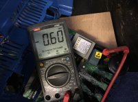
Hey JST, sorry I have been away for a few days. I checked the resistance between the output terminals and the +/- capacitor terminals and got the results shown in the pictures. These first 3 are from each output terminal to one side of the capacitor and the following 3 are from each of the output terminals to the other side.

IMG_7363.jpgIMG_7371.jpgIMG_7381.jpg
 
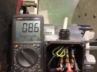
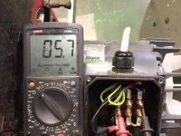
Then also, the measurements on the motor itself between the terminals...between each and earth was open circuit.

IMG_7319.jpgIMG_7325.jpgIMG_7333.jpg
 
If the measurements are as you say, that one o.oo in the second set of measurements looks bad. Repeat it using the range marked with the diode symbol that is just below the 20M range. That has the voltage to check a diode.

In fact, for that set of measurements, repeat all three, on that range, first with the leads one way, and again with the red and black leads reversed.

However, that0.00 looks a lot as if there is a bad IGBT, if you are certain you could not have had the leads shorted to one another, or touching something other than a motor terminal and the + or - bus.
 
I repeated and got the same results, (beeping from the diode setting) I went through and used the diode check on the heatsunk individual transistors along the edge of the board and the first one yielded different results to the rest in that any combo of 2 pins was a short so I removed that one, same result on the bench. Trouble is I cannot find the part number online, any ideas?

IMG_7439.jpg
 
Well, it's an obsolete 600V IGBT. I did find a data sheet on-line. They were made in two types, one with a diode (suffix FD) and one without (suffix F). Yours may be the no diode type, in which case there are diodes in the thing also.

At least it is old enough to have replaceable parts. The problem is finding a part that will work. Since they are "insulated gate" types, you need to remove them with precautions against static electricity. Unless you do, I can pretty well guarantee they will not be good, the usual failure rate without precautions is around 50 to 75%/

The "gate driver " IC will almost certainly also be bad, and there may be other bad parts as well. OK if you have access to parts, and are reasonably skilled with electronics. Otherwise not.

http://www.irf.com/product-info/datasheets/data/irgbc20f.pdf


Back
Top